Computers and industrial control
Introduction
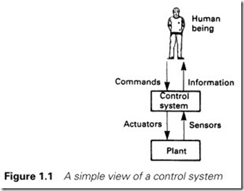
Very few industrial plants can be left to run themselves, and most need some form of control system to ensure safe and economical operation. Figure 1.1 is thus a representation of a typical installation, consisting of a plant connected to a control system. This acts to translate the commands of the human operator into the required actions, and to display the plant status back to the operator.
At the simplest level, the plant could be an electric motor driving a cooling fan. Here the control system would be an electrical starter with protection against motor overload and cable faults. The operator controls would be start/stop pushbuttons and the plant status displays simply running/stopped and fault lamps.
At the other extreme, the plant could be a vast petrochemical installation. Here the control system would be complex and a mixture of technologies. The link to the human operators will be equally varied, with commands being given and information displayed via many devices.
In most cases the operator will be part of the control system. If an alarm light comes on saying ‘Low oil level’ the operator will be expected to add more oil.
Types of control strategies
It is very easy to be confused and overwhelmed by the size and complexity of large industrial processes. Most, if not all, can be simplified by considering them to be composed of many small sub- processes. These sub-processes can generally be considered to fall into three distinct areas.
Monitoring subsystems
These display the process state to the operator and draw attention to abnormal or fault conditions which need attention. The plant condition is measured by suitable sensors.
Digital sensors measure conditions with distinct states. Typical examples are running/stopped, forward/off/reverse, fault/healthy, idle/low/medium/high, high level/normal/low level. Analog sensors measure conditions which have a continuous range such as temperature, pressure, flow or liquid level.
The results of these measurements are displayed to the operator via indicators (for digital signals) or by meters and bargraphs for analog signals.
The signals can also be checked for alarm conditions. An overtravel limit switch or an automatic trip of an overloaded motor are typical digital alarm conditions. A high temperature or a low liquid level could be typical analog alarm conditions. The operator could be informed of these via warning lamps and an audible alarm.
A monitoring system often keeps records of the consumption of energy and materials for accountancy purposes, and produces an event/ alarm log for historical maintenance analysis. A pump, for example, may require maintenance after 5000 hours of operation.
Sequencing subsystems
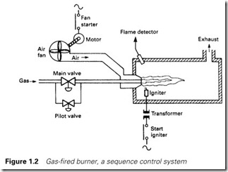
Many processes follow a predefined sequence. To start the gas burner of Figure 1.2, for example, the sequence could be:
(a) Start button pressed; if sensors are showing sensible states (no air flow and no flame) then sequence starts.
(b) Energize air fan starter. If starter operates (checked by contact on starter) and air flow is established (checked by flow switch) then
(c) Wait two minutes (for air to clear out any unburnt gas) and then
(d) Open gas pilot valve and operate igniter. Wait two seconds and then stop igniter and
(e) If flame present (checked by flame failure sensor) open main gas valve.
(f) Sequence complete. Burner running. Stays on until stop button pressed, or air flow stops, or flame failure.
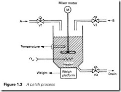
The above sequence works solely on digital signals, but sequences can also use analog signals. In the batch process of Figure 1.3 analog sensors are used to measure weight and temperature to give the sequence:
1 Open valve V1 until 250 kg of product A have been added.
2 Start mixer blade.
3 Open valve V2 until 310 kg of product B have been added.
4 Wait 120 s (for complete mixing).
5 Heat to 80 °C and maintain at 80 °C for 10 min.
6 Heater off. Allow to cool to 30 °C.
7 Stop mixer blade.
8 Open drain valve V3 until weight less than 50 kg.
Closed loop control subsystems
In many analog systems, a variable such as temperature, flow or pressure is required to be kept automatically at some preset value or made to follow some other signal. In step 5 of the batch sequence above, for example, the temperature is required to be kept constant to 80 °C within quite narrow margins for 10 minutes.
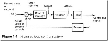
Such systems can be represented by the block diagram of Figure 1.4. Here a particular characteristic of the plant (e.g. temperature) denoted by PV (for process variable) is required to be kept at a preset value SP (for setpoint). PV is measured by a suitable sensor and compared with the SP to give an error signal
error = SP – PV (1.1)
If, for example, we are dealing with a temperature controller with a setpoint of 80 °C and an actual temperature of 78 °C, the error is 2 °C.
This error signal is applied to a control algorithm. There are many possible control algorithms, and this topic is discussed in detail in Chapter 4, but a simple example for a heating control could be ‘If the error is negative turn the heat off, if the error is positive turn the heat on.’
The output from the control algorithm is passed to an actuator which affects the plant. For a temperature control, the actuator could be a heater, and for a flow control the actuator could be a flow control valve.
The control algorithm will adjust the actuator until there is zero error, i.e. the process variable and the setpoint have the same value.
In Figure 1.4, the value of PV is fed back to be compared with the setpoint, leading to the term ‘feedback control’. It will also be noticed that the block diagram forms a loop, so the term ‘closed loop control’ is also used.
Because the correction process is continuous, the value of the controlled PV can be made to track a changing SP. The air/gas ratio for a burner can thus be maintained despite changes in the burner firing rate.
Control devices
The three types of control strategy outlined above can be achieved in many ways. Monitoring/alarm systems can often be achieved by connecting plant sensors to displays, indicators and alarm annunciators. Sometimes the alarm system will require some form of logic. For example, you only give a low hydraulic pressure alarm if the pumps are running, so a time delay is needed after the pump starts to allow the pressure to build up. After this time, a low pressure causes the pump to stop (in case the low pressure has been caused by a leak).
Sequencing systems can be built from relays combined with timers, uniselectors and similar electromechanical devices. Digital logic (usually based on TTL or CMOS integrated circuits) can be used for larger systems (although changes to printed circuit boards are more difficult to implement than changes to relay wiring). Many machine tool applications are built around logic blocks: rail-mounted units containing logic gates, storage elements, timers and counters which are linked by terminals on the front of the blocks to give the required operation. As with a relay system, commissioning changes are relatively easy to implement.
Closed loop control can be achieved by controllers built around DC amplifiers such as the ubiquitous 741. The ‘three-term controller’
(described further in Chapter 4) is a commercially available device that performs the function of Figure 1.4. In the chemical (and particularly the petrochemical) industries, the presence of potentially explosive atmospheres has led to the use of pneumatic controllers, with the signals in Figure 1.4 being represented by pneumatic pressures.
Enter the computer
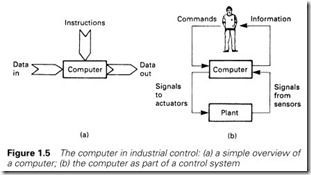
A computer is a device that performs predetermined operations on input data to produce new output data, and as such can be represented by Figure 1.5(a). For a computer used for payroll calculations the input data would be employees’ names, salary grades and hours worked. These data would be operated on according to instructions written to include current tax and pension rules to produce output data in the form of wage slips (or, today, more likely direct transfers to bank accounts).
Early computer systems were based on commercial functions: payroll, accountancy, banking and similar activities. The operations tended to be batch processes, a daily update of stores stock, for example.
The block diagram of Figure 1.5(a) has a close relationship with the control block of Figure 1.1, which could be redrawn, with a computer pro- viding the control block, as in Figure 1.5(b). Note that the operator’s actions (e.g. start process 3) are not instructions, they are part of the input data. The instructions will define what action is to be taken as the input data (from both the plant and the operator) change. The output data are control actions to the plant and status displays to the operator.
Early computers were large, expensive and slow. Speed is not that important for batch-based commercial data processing (commercial
programmers will probably disagree!) but is of the highest priority in industrial control, which has to be performed in ‘real time’. Many emer- gency and alarm conditions require action to be taken in fractions of a second.
Commercial (with the word ‘commercial’ used to mean ‘designed for use in commerce’) computers were also based on receiving data from punched cards and keyboards and sending output data to printers. An industrial process requires possibly hundreds of devices to be read in real time and signals sent to devices such as valves, motors, meters and so on.
There was also an environmental problem. Commercial computers are designed to exist in an almost surgical atmosphere; dust-free and an ambient temperature that can only be allowed to vary by a few degrees. Such conditions can be almost impossible to achieve close to a manufac- turing process.
The first industrial computer application was probably a monitoring system installed in an oil refinery in Port Arthur, USA in 1959. The reli- ability and mean time between failure of computers at this time meant that little actual control was performed by the computer, and its role approximated to the earlier Section 1.2.1.
Computer architectures
It is not essential to have intimate knowledge of how a computer works before it can be used effectively, but an appreciation of the parts of a com- puter is useful for appreciating how a computer can be used for industrial control.
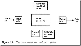
Figure 1.5(a) can be expanded to give the more detailed layout of Figure 1.6. This block diagram (which represents the whole computing range from the smallest home computer to the largest commercial mainframe) has six portions:
1 An input unit where data from the outside world are brought into the computer for processing.
2 A store, or memory, which will be used to store the instructions the computer will follow and data for the computer to operate on. These data can be information input from outside or intermediate results calculated by the machine itself. The store is organized into a number of boxes, each of which can hold one number and is identi- fied by an address as shown in Figure 1.7. Computers work inter- nally in binary (see the Appendix for a description of binary, hexadecimal (hex) and other number systems) and the store does not distinguish between the meanings that could be attached to the data stored in it. For example, in an 8-bit computer (which works with numbers 8 bits long in its store) the number 01100001 can be interpreted as:
(a) The decimal number 97.
(b) The hex number 61 (see Appendix).
(c) The letter ‘a’ (see Chapter 6).
(d) The state of eight digital signals such as limit switches.
(e) An instruction to the computer. If the machine was the old Z80 microprocessor, hex 61 moves a number between two internal stores.
A typical desktop computer will use 16-bit numbers (called a 16-bit word) and have over a million store locations. The industrial computers we will be mainly discussing have far smaller storage, 32 000 to 64 000
store locations being typical for larger control machines, but even smaller machines with just 1000 store locations are common.
3 Data from the store can be accessed very quickly, but commercial computers often need vast amounts of storage to hold details such as bank accounts or names and addresses. This type of data is not required particularly quickly and is held in external storage. This is usually magnetic disks or tapes and is called secondary or backing storage. Such stores are not widely used on the types of computer we will be discussing.
4 An output unit where data from the computer are sent to the outside world.
5 An arithmetic and logical unit (called an ALU) which performs operations on the data held in the store according to the instructions the machine is following.
6 A control unit which links together the operations of the other five units. Often the ALU and the control unit are known, together, as the central processor unit or CPU. A microprocessor is a CPU in a single integrated circuit.
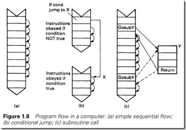
The instructions the computer follows are held in the store and, with a few exceptions which we will consider shortly, are simply followed in sequential order as in Figure 1.8(a).
The control unit contains a counter called an instruction register (or IR) which says at which address in the store the next instruction is to be
found. Sometimes the name program counter (and the abbreviation PC) is used.
When each instruction is obeyed, the control unit reads the store location whose address is held in the IR. The number held in this store location tells the control unit what instruction is to be performed.
Instructions nearly always require operations to be performed on data in the store (e.g. add two numbers) so the control unit will bring data from the store to the ALU and perform the required function.
When the instruction has been executed, the control unit will increment the IR so it holds the address of the next instruction.
There are surprisingly few types of instruction. The ones available on most microprocessors are variations on:
1 Move data from one place to another (e.g. input data to a store location, or move data from a store location to the ALU).
2 ALU operations on two data items, one in the ALU and one in a specified store location. Operations available are usually add, subtract, and logical operations such as AND, OR.
3 Jumps. In Figure 1.8(a) we implied that the computer followed a simple sequential list of instructions. This is usually true, but there are occa- sions where simple tests are needed. These usually have the form
IF (some condition) THEN Perform some instructions
ELSE
Perform some other instructions
To test a temperature, for example, we could write IF Temperature is less than 75 °C THEN
Turn healthy light on
Turn fault light off ELSE
Turn healthy light off Turn fault light on
Such operations use conditional jumps. These place a new address into the IR dependent on the last result in the accumulator. Conditional jumps can be specified to occur for outcomes such as result positive, result negative or result zero, and allow a program to follow two alternative routes as shown in Figure 1.8(b).
4 Subroutines. Many operations are required time and time again within the same program. In an industrial control system using flows measured by orifice plates, a square root function will be required many times (flow is proportional to the square root of the pressure drop across the orifice plate). Rather than write the same instruction sev- eral times (which is wasteful of effort and storage space) a subroutine instruction allows different parts of the program to temporarily transfer operations to a specified subroutine, returning to the instruc- tion after the subroutine call as shown in Figure 1.8(c).
Machine code and assembly language programming
The series of instructions that we need (called a ‘program’) has to be written and loaded into the computer. At the most basic level, called machine code programming, the instructions are written into the machine in the raw numerical form used by the machine. This is difficult to do, prone to error, and almost impossible to modify afterwards.
The sequence of numbers
16 00 58 21 00 00 06 08 29 17 D2 0E 40 19 05 C2 08 40 C9
genuinely are the instructions for a multiplication subroutine starting at address 4000 for a Z80 microprocessor, but even an experienced Z80 programmer would need reference books (and a fair amount of time) to work out what is going on with just these 19 numbers.
Assembly language programming uses mnemonics instead of the raw code, allowing the programmer to write instructions that can be rela- tively easily followed. For example, with
LOAD Temperature
SUB 75
JUMP POSITIVE to Fault_Handler
it is fairly easy to work out what is happening.
A (separate) computer program called an assembler converts the programmer’s mnemonic-based program (called the source) into an equivalent machine code program (called the object) which can then be run.
Writing programs in assembly language is still labour-intensive, however, as there is one assembly language instruction for each machine code instruction.
High level languages
Assembly language programming is still relatively difficult to write, so ways of writing computer programs in a style more akin to English were developed. This is achieved with so-called ‘high level languages’ of which the best known are probably Pascal, FORTRAN and the ubiquitous BASIC (and there are many, many languages: RPG, FORTH, LISP, CORAL and C to name but a few, each with its own attractions).
In a high level language, the programmer writes instructions in some- thing near to English. The Pascal program below, for example, gives a printout of a requested multiplication table.
program multtable (input, output); var number, count : integer begin readln (‘Which table do you want’, number); for count = 1 to 10 do writeln (count, ‘times’, number, ‘is’, count*number); end. (of program)
Even though the reader may not know Pascal, the operation of the program is clear (if asked to change the table from a ten times table to a twenty times table, for example, it is obvious which line would need to be changed).
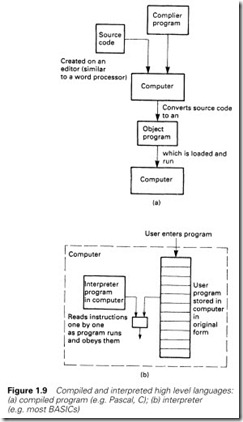
A high level language source program can be made to run in two distinct ways. A compiler is a program which converts the entire high level source program to a machine code object program offline. The resultant object program can then be run independently of the source program or the compiler.
With an interpreter, the source program and the interpreter both exist in the machine when the program is being run. The interpreter scans each line of source code, converting them to equivalent machine code instructions as they are obeyed. There is no object program with an interpreter.
A compiled program runs much faster than an interpreted program (typically five to ten times as fast because of the extra work that the inter- preter has to do) and the compiled object program will be much smaller than the equivalent source code program for an interpreter. Compilers are, however, much less easy to use, a typical sequence being:
1 A text editor is loaded into the computer.
2 The source program is typed in or loaded from disk (for modification).
3 The resultant source file is saved to disk.
4 The compiler is loaded from disk and run.
5 The source file is loaded from disk.
6 Compilation starts (this can take several minutes). If any errors are found go back to step 1.
7 An object program is produced which can be saved to disk and/or run. If any runtime errors are found, go back to step 1.
An interpreted language is much easier to use, and for many applications the loss of speed is not significant. BASIC is usually an interpreted language; Pascal, C and Fortran are usually compiled. Figure 1.9 sum- marizes the operation of compiled and interpreted high level languages.
Application programs
Increasingly, as computers become more widespread, many programs have been written which allow the user to define the tasks to be performed without worrying unduly about how the computer achieves them. These are known as application programs and are typified by spreadsheets such as Lotus 123 and Excel and databases such as Approach and Access. In these the user is defining complex mathematical or database operations without ‘programming’ the computer in a conven- tional sense.
Requirements for industrial control
Industrial control has rather different requirements than other applica- tions. It is worth examining these in some detail.
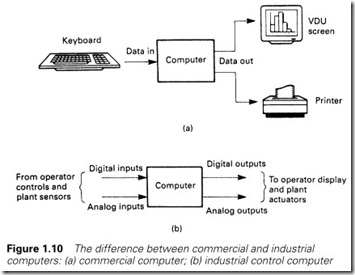
A conventional computer, shown schematically in Figure 1.10(a), takes data usually from a keyboard and outputs data to a VDU screen or printer. The data being manipulated will generally be characters or numbers (e.g. item names and quantities held in a stores stock list).
The control computer of Figure 1.10(b) is very different. Its inputs come from a vast number of devices. Although some of these are numeric (flows, temperature, pressures and similar analog signals) most will be single-bit, on/off, digital signals.
There will also be a similarly large amount of digital and analog output signals. A very small control system may have connections to about 20 input and output signals; figures of over 200 connections are quite common on medium-sized systems. The keyboard, VDU and printer may exist, but they are not necessary, and their functions will probably be different to those on a normal desktop or mainframe computer.
Although it is possible to connect this quantity of signals to a conven- tional machine, it requires non-standard connections and external boxes. Similarly, although programming for a large amount of input and output signals can be done in Pascal, BASIC or C, the languages are being used for a purpose for which they were not really designed, and the result can be very ungainly.
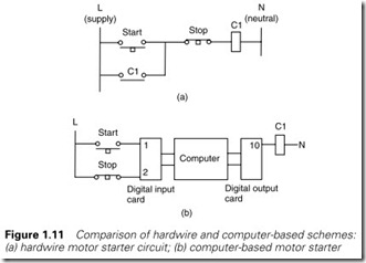
In Figure 1.11(a), for example, we have a simple motor starter. This could be connected as a computer-driven circuit as in Figure 1.11(b). The two inputs are identified by addresses 1 and 2, with the output (the relay starter) being given the address 10.
If we assume that a program function bitread (N) exists which gives the state (on/off) of address N, and a procedure bitwrite (M,var) which sends the state of program variable var to address M, we could give the actions of Figure 1.11 by repeat
start: = bitread(1);
stop: = bitread(2);
run: = ((start) or (run)) & stop;
bitwrite (10,run);
until hellfreezesover
where start, stop and run are 1-bit variables. The program is not very clear, however, and we have just three connections.
An industrial control program rarely stays the same for the whole of its life. There are always modifications to cover changes in the oper- ations of the plant. These changes will be made by plant maintenance staff, and must be made with minimal (preferably no) interruptions to the plant production. Adding a second stop button and a second start button to Figure 1.11 would not be a simple task.
In general, computer control is done in real time, i.e. the computer has to respond to random events as they occur. An operator expects a motor to start (and more important to stop!) within a fraction of a second of the button being pressed. Although commercial computing needs fast computers, it is unlikely that the difference between one and two second computation time for a spreadsheet would be noticed by the user. Such a difference would be unacceptable for industrial control.
Time itself is often part of the control strategy (e.g. start air fan, wait 10 s for air purge, open pilot gas valve, wait 0.5 s, start ignition spark, wait 2.5 s, if flame present open main gas valve). Such sequences are difficult to write with conventional languages.
Most control faults are caused by external items (limit switches, solen- oids and similar devices) and not by failures within the central control itself. The permission to start a plant, for example, could rely on signals involving cooling water flows, lubrication pressure, or temperatures within allowable ranges. For quick fault finding the maintenance staff must be able to monitor the action of the computer program whilst it is running. If, as is quite common, there are ten interlock signals which allow a motor to start, the maintenance staff will need to be able to check these quickly in the event of a fault. With a conventional computer, this could only be achieved with yet more complex programming.
The power supply in an industrial site is shared with many antisocial loads; large motors stopping and starting, thyristor drives which put spikes and harmonic frequencies onto the mains supply. To a human these are perceived as light flicker; in a computer they can result in storage corruption or even machine failure.
An industrial computer must therefore be able to live with a ‘dirty’ mains supply, and should also be capable of responding sensibly following a total supply interruption. Some outputs must go back to the state they were in before the loss of supply; others will need to turn off or on until an operator takes available corrective action. The designer must have the facility to define what happens when the system powers up from cold.
The final considerations are environmental. A large mainframe com- puter generally sits in an air-conditioned room at a steady 20 °C with carefully controlled humidity. A desktop PC will normally live in a fairly constant environment because human beings do not work well at extremes. An industrial computer, however, will probably have to operate away from people in a normal electrical substation with temperatures as low as -10 °C after a winter shutdown, and possibly over 40 °C in the height of summer. Even worse, these temperature variations lead to a constant expansion and contraction of components which can lead to early failure if the design has not taken this factor into account.
To these temperature changes must be added dust and dirt. Very few industrial processes are clean, and the dust gets everywhere (even with IP55 cubicles, because an IP55 cubicle is only IP55 when the doors are shut and locked; IP ratings are discussed in Section 8.4.2). The dust will work itself into connectors, and if these are not of the highest quality, intermittent faults will occur which can be very difficult to find.
In most computer applications, a programming error or a machine fault can at worst be expensive and embarrassing. When a computer controlling a plant fails, or a programmer misunderstands the plant’s operation, the result could be injuries or fatalities. Under the UK Health and Safety at Work Act, prosecution of the design engineers could result. It behoves everyone to take extreme care with the design.
Our requirements for an industrial control computer are very demanding, and it is worth summarizing them:
1 They should be designed to survive in an industrial environment with all that this implies for temperature, dirt and poor quality mains supply.
2 They should be capable of dealing with bit-form digital input/output signals at the usual voltages encountered in industry (24 V DC to 240 V AC) plus analog input/output signals. The expansion of the I/O should be simple and straightforward.
3 The programming language should be understandable by main- tenance staff (such as electricians) who have no computer training. Programming changes should be easy to perform in a constantly changing plant.
4 It must be possible to monitor the plant operation whilst it is running to assist fault finding. It should be appreciated that most faults will be in external equipment such as plant-mounted limit switches, actuators and sensors, and it should be possible to observe the action of these from the control computer.
5 The system should operate sufficiently fast for realtime control. In practice, ‘sufficiently fast’ means a response time of around 0.1 s, but this can vary depending on the application and the controller used.
6 The user should be protected from computer jargon.
7 Safety must be a prime consideration.
The programmable controller
In the late 1960s the American motor car manufacturer General Motors was interested in the application of computers to replace the relay sequencing used in the control of its automated car plants. In 1969 it produced a specification for an industrial computer similar to that outlined at the end of Section 1.3.5.
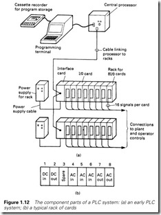
Two independent companies, Bedford Associates (later called Modicon) and Allen Bradley, responded to General Motor’s specification. Each produced a computer system similar to Figure 1.12 which bore little resemblance to the commercial minicomputers of the day.
The computer itself, called the central processor, was designed to live in an industrial environment, and was connected to the outside world via racks into which input or output cards could be plugged. In these early machines there were essentially four different types of cards:
1 DC digital input card
2 DC digital output card
3 AC digital input card
4 AC digital output card
Each card would accept 16 inputs or drive 16 outputs. A rack of eight cards could thus be connected to 128 devices. It is very important to appreciate that the card allocations were the user’s choice, allowing great flexibility. In Figure 1.12(b) the user has installed one DC input card, one DC output card, three AC input cards, and two AC output cards, leaving one spare position for future expansion. This rack can thus be connected to
· 16 DC input signals
· 16 DC output signals
· 48 AC input signals
· 16 AC output signals
Not all of these, of course, need to be used.
The most radical idea, however, was a programming language based on a relay schematic diagram, with inputs (from limit switches, push- buttons, etc.) represented by relay contacts, and outputs (to solenoids, motor starters, lamps, etc.) represented by relay coils. Figure 1.13 shows a simple hydraulic cylinder which can be extended or retracted by pushbuttons. Its stroke is set by limit switches which open at the end of travel, and the solenoids can only be operated if the hydraulic pump is running. This would be controlled by the computer program of
Figure 1.13(b) which is identical to the relay circuit needed to control the cylinder. These programs look like the rungs on a ladder, and were consequently called ‘ladder diagrams’.
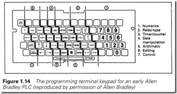
The program was entered via a programming terminal with keys showing relay symbols (normally open/normally closed contacts, coils, timers, counters, parallel branches, etc.) with which a maintenance electrician would be familiar. Figure 1.14 shows the programmer
keyboard for an early PLC. The meaning of the majority of the keys should be obvious. The program, shown exactly on the screen as in Figure 1.13(b), would highlight energized contacts and coils, allowing the programming terminal to be used for simple fault finding.
The processor memory was protected by batteries to prevent corruption or loss of program during a power fail. Programs could be stored on cassette tapes which allowed different operating procedures (and hence programs) to be used for different products.
The name given to these machines was ‘programmable controllers’ or PCs. The name ‘programmable logic controller’ or PLC was also used, but this is, strictly, a registered trademark of the Allen Bradley Company. Unfortunately in more recent times the letters PC have come to be used
for personal computer, and confusingly the worlds of programmable controllers and personal computers overlap where portable and lap-top computers are now used as programming terminals. To avoid confusion, we shall use PLC for a programmable controller and PC for a personal computer. Section 2.12 gives examples of programming software on modern PCs.
Input/output connections
Input cards
Internally a computer usually operates at 5 V DC. The external devices (solenoids, motor starters, limit switches, etc.) operate at voltages up to 110 V AC. The mixing of these two voltages will cause severe and possibly irreparable damage to the PLC electronics. Less obvious problems can occur from electrical ‘noise’ introduced into the PLC from voltage spikes on signal lines, or from load currents flowing in AC neutral or DC return lines. Differences in earth potential between the PLC cubicle and outside plant can also cause problems.
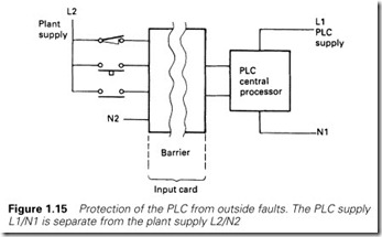
The question of noise is discussed at length in Chapter 8, but there are obviously very good reasons for separating the plant supplies from the PLC supplies with some form of electrical barrier as in Figure 1.15. This ensures that the PLC cannot be adversely affected by anything happening on the plant. Even a cable fault putting 415 V AC onto a DC input would only damage the input card; the PLC itself (and the other cards in the system) would not suffer.
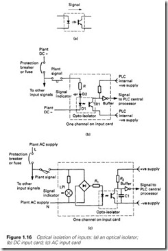
This is achieved by optical isolators, a light-emitting diode and photo- electric transistor linked together as in Figure 1.16(a). When current is passed through the diode D1 it emits light, causing the transistor TR1 to
switch on. Because there are no electrical connections between the diode and the transistor, very good electrical isolation (typically 1–4 kV) is achieved.
A DC input can be provided as in Figure 1.16(b). When the push- button is pressed, current will flow through D1, causing TR1 to turn on, passing the signal to the PLC internal logic. Diode D2 is a light-emitting diode used as a fault-finding aid to show when the input signal is present. Such indicators are present on almost all PLC input and output cards. The resistor R sets the voltage range of the input. DC input cards are usually available for three voltage ranges: 5 V (TTL), 12–24 V, 24–50 V. A possible AC input circuit is shown in Figure 1.16(c). The bridge rectifier is used to convert the AC to full wave rectified DC. Resistor R2 and capacitor C1 act as a filter (of about 50 ms time constant) to give a clean signal to the PLC logic. As before, a neon LP1 acts as an input signal indicator for fault finding, and resistor R1 sets the voltage range.
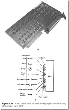
Figure 1.17(a) shows a typical input card from the Allen Bradley range. The isolation barrier and monitoring LEDs can be clearly seen. This card handles eight inputs and could be connected to the outside world as in Figure 1.17(b).
Output connections
Output cards again require some form of isolation barrier to limit damage from the inevitable plant faults and also to stop electrical ‘noise’ corrupting the processor’s operations. Interference can be more of a problem on outputs because higher currents are being controlled by
the cards and the loads themselves are often inductive (e.g. solenoid and relay coils).
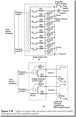
There are two basic types of output card. In Figure 1.18(a), eight outputs are fed from a common supply, which originates local to the PLC cubicle (but separate from the supply to the PLC itself). This arrangement is the simplest and the cheapest to install. Each output has its own individual fuse protection on the card and a common circuit breaker. It is important to design the system so that a fault, say, on load 3 blows the fuse FS3 but does not trip the supply to the whole card, shutting down every output. This topic, called ‘discrimination’, is discussed further in Chapter 8.
A PLC frequently has to drive outputs which have their own individual supplies. A typical example is a motor control centre (MCC) where each starter has a separate internal 110-V supply derived from the 415-V bars. The card arrangement of Figure 1.18(a) could not be used here without separate interposing relays (driven by the PLC with contacts into the MCC circuit).
An isolated output card, shown in Figure 1.18(b), has individual out- puts and protection and acts purely as a switch. This can be connected directly with any outside circuit. The disadvantage is that the card is more complicated (two connections per output) and safety becomes more involved. An eight-way isolated output card, for example, could have voltage on its terminals from eight different locations.
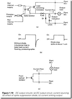
Contacts have been shown on the outputs in Figure 1.18. Relay outputs can be used (and do give the required isolation) but are not particularly common. A relay is an electromagnetic device with moving parts and hence a finite limited life. A purely electronic device will have greater reliability. Less obviously, though, a relay-driven inductive load can generate troublesome interference and lead to early contact failure.
A transistor output circuit is shown in Figure 1.19(a). Optical isolation is again used to give the necessary separation between the plant and the PLC system. Diode D1 acts as a spike suppression diode to reduce the voltage spike encountered with inductive loads. Figure 1.19(b) shows the effect. The output state can be observed on LED1. Figure 1.19(a) is a current sourcing output. If NPN transistors are used, a current sinking card can be made as in Figure 1.19(c).
AC output cards invariably use triacs, a typical circuit being shown in Figure 1.20(a). Triacs have the advantage that they turn off at zero current in the load, as shown in Figure 1.20(b), which eliminates the interference as an inductive load is turned off. If possible, all AC loads should be driven from triacs rather than relays.
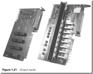
Figure 1.21 is a photograph of the construction of AC and DC output cards; the isolation barrier, the state indication LEDs and the protection fuses can be clearly seen.
An output card will have a limit to the current it can supply, usually set by the printed circuit board tracks rather than the output devices. An individual output current will be set for each output (typically 2 A) and a total overall output (typically 6 A). Usually the total allowed for the card current is lower than the sum of the allowed individual outputs. It is
therefore good practice to reduce the total card current by assigning outputs which cannot occur together (e.g. forward/reverse, fast/slow) to the same card.
Input/output identification
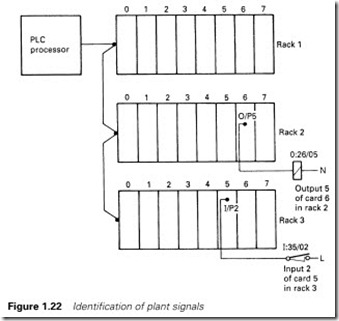
The PLC program must have some way of identifying inputs and out- puts. In general, a signal is identified by its physical location in some form of mounting frame or rack, by the card position in this rack, and by which connection on the card the signal is wired to.
In Figure 1.22, a lamp is connected to output 5 on card 6 in rack 2. In Allen Bradley notation, this is signal
O:26/05
The pushbutton is connected to input 2 on card 5 in rack 3, and (again in Allen Bradley notation) is
I:35/02
Most PLC manufacturers use a similar scheme. The topic is discussed further in Chapter 2.
Remote I/O
So far we have assumed that a PLC consists of a processor unit and a collection of I/O cards mounted in local racks. Early PLCs did tend to be arranged like this, but in a large and scattered plant with this arrange- ment, all signals have to be brought back to some central point in expensive multicore cables. It will also make commissioning and fault finding rather difficult, as signals can only be monitored effectively at a point possibly some distance from the device being tested.
In all bar the smallest and cheapest systems, PLC manufacturers therefore provide the ability to mount I/O racks remote from the processor, and link these racks with simple (and cheap) screened single
pair or fibre optic cable. Racks can then be mounted up to several kilometres away from the processor.
There are many benefits from this. It obviously reduces cable costs as racks can be laid out local to the plant devices and only short multicore cable runs are needed. The long runs will only need the communication cables (which are cheap and only have a few cores to terminate at each end) and hardwire safety signals (which should not be passed over remote I/O cable, or even through a PLC for that matter, a topic discussed further in Chapter 8).
Less obviously, remote I/O allows complete units to be built, wired to a built-in rack, and tested offsite prior to delivery and installation. The pulpit in Figure 3.2 contains three remote racks, and connects to the controlling PLC mounted in a substation about 500 m away, via a remote I/O cable, plus a few power supplies and hardwire safety signals. This allowed the pulpit to be built and tested before it arrived on site. Similar ideas can be applied to any plant with I/O that needs to be connected to a PLC.
If remote I/O is used, provision should be made for a program terminal to be connected local to each rack. It negates most of the benefits if the designer can only monitor the operation from a central control room several hundred metres from the plant. Fortunately, manufacturers have recognized this and most allow programming terminals to be connected to the processor via similar screened twin cable.
We will discuss serial communication further in Chapter 5.
The advantages of PLC control
Any control system goes through four stages from conception to a working plant. A PLC system brings advantages at each stage.
The first stage is design; the required plant is studied and the control strategies decided. With conventional systems design must be complete before construction can start. With a PLC system all that is needed is a possibly vague idea of the size of the machine and the I/O requirements (how many inputs and outputs). The input and output cards are cheap at this stage, so a healthy spare capacity can be built in to allow for the inevitable omissions and future developments.
Next comes construction. With conventional schemes, every job is a ‘one-off’ with inevitable delays and costs. A PLC system is simply bolted together from standard parts. During this time the writing of the PLC program is started (or at least the detailed program specification is written).
The next stage is installation, a tedious and expensive business as sensors, actuators, limit switches and operator controls are cabled. A distributed PLC system (discussed in Chapter 5) using serial links and pre-built and tested desks can simplify installation and bring huge cost benefits. The majority of the PLC program is written at this stage.
Finally comes commissioning, and this is where the real advantages are found. No plant ever works first time. Human nature being what it is, there will be some oversights. Changes to conventional systems are time consuming and expensive. Provided the designer of the PLC system has built in spare memory capacity, spare I/O and a few spare cores in multicore cables, most changes can be made quickly and relatively cheaply. An added bonus is that all changes are recorded in the PLC’s program and commissioning modifications do not go unrecorded, as is often the case in conventional systems.
There is an additional fifth stage, maintenance, which starts once the plant is working and is handed over to production. All plants have faults, and most tend to spend the majority of their time in some form of failure mode. A PLC system provides a very powerful tool for assisting with fault diagnosis. This topic is discussed further in Chapter 8.
A plant is also subject to many changes during its life to speed pro- duction, to ease breakdowns or because of changes in its requirements. A PLC system can be changed so easily that modifications are simple and the PLC program will automatically document the changes that have been made.
