INDUCTION MOTOR RATINGS
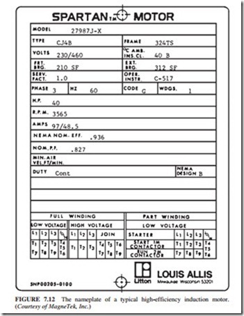
Figure 7.12 shows a nameplate for a typical high-efficiency induction motor. The most important ratings are
1. Output power
2. Voltage
3. Current
4. Power factor
5. Speed
6. Nominal efficiency
7. NEMA design class
8. Starting code
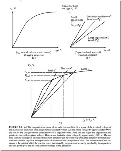
(b) Plot of the voltage-current characteristic of a capacitor bank. Note that the larger the capacitance, the greater its current for a given voltage. This current leads the phase voltage by approximately 90°. (c) The no- load terminal voltage for an isolated induction generator can be found by plotting the generator terminal characteristic and the capacitor voltage-current characteristic on a single set of axes. The intersection of the two curves is the point at which the reactive power demanded by the generator is exactly supplied by the capacitors, and this point gives the no-load terminal voltage of the generator.
The voltage limit is based on the maximum acceptable magnetization current flow because as the voltage increases, the iron becomes more saturated and the magnetization current increases. A 60-Hz induction motor can be used on a 50-Hz power system only if the voltage rating is decreased by the same proportion as the decrease in frequency. The current limit is based on the maximum acceptable heating in the motor’s windings. The power limit is determined by the combination of the voltage and current ratings with the power factor and efficiency.


