Objectives
After studying this unit, the student will be able to:
• List the principal parts of a programmable controller
• Describe the differences between programmable controllers and other types of computers
• Discuss the operation of the programming terminal, the central processor, and the 1/0 track
• Draw basic diagrams of how the input and output modules function
Programmable controllers were first used by the automobile industry in the late 1960s. Each time a change was made in design, it was neces sary to change the control systems operating the machinery. This consisted of physically rewiring the control system to make it perform the new op eration. Rewiring the system, of course, was ex tremely time consuming and costly. What the in dustry needed was some type of control system that could be changed without the extensive rewir ing required to change relay control systems.
One of the first questions that is generally asked is, “Is a programmable controller a com puter?” The answer to that question is “yes.” The programmable controller, or PC, is a special com puter designed to perform a special function.
DIFFERENCES BETWEEN THE PC AND THE COMMON COMPUTER
Some differences between a PC and a home and business computer are:
1. The PC is designed to be operated in an in dustrial environment. Any computer used in industry must be able to operate in extremes of temperature, ignore voltage spikes and drops on the incoming power line, survive in an atmosphere that often contains corrosive vapors, oil, and dirt, and withstand shock and vibration.
2. Most programmable controllers are designed to be programmed with relay schematic or ladder diagrams instead of the common com puter languages such as Basic or Fortran. An electrician who is familiar with relay logic diagrams can generally be trained to program a PC in a few hours, whereas it generally takes several months to train someone to program a standard computer.
BASIC COMPONENTS
Programmable controllers can be divided into four basic parts:
A. The power supply
B. The central processing unit
C. The program loader or terminal
D. The I/0 (pronounced eye-oh) track
The Power Supply
The power supply is used to lower the incom ing ac voltage to the desired level, rectify it to di rect current, and then filter and regulate it. The internal logic circuits of programmable controllers operate on 5 to 15 volts de depending on the type of controller. This voltage must be free of voltage spikes and other electrical noise. It must also be regulated to within 5% of the required voltage value. Some manufacturers of PCs use a separate power supply, and others build the power supply into the central processor.
The CPU
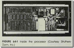
The central processing unit, or CPU, is the brain of the programmable controller. n contains the microprocessor chip and related integrated cir cuits to perform all the logic functions. The microprocessor chip used in most PCs is the same as the common computer chip used in many home and business machines, figure 64-1.
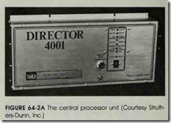
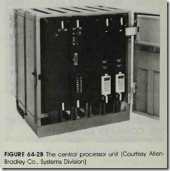
The central processing unit generally has a key switch located on the front panel. This switch must be turned on before the CPU can be pro grammed . This is done to prevent the circuit from being changed accidently. Plug connections mounted on the central processor are used to pro vide connections for the programming terminal and the I/0 tracks, figures 64-2A and 64-2B. Most CPUs are designed so that once the program has been tested, it can be stored on tape or disc. In this way if a central processing unit fails and has to be replaced, the new unit can be reprogrammed from the tape or disc. This eliminates the time consuming process of having to reprogram by hand.
The Programming Terminal
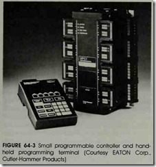
The programming terminal or loading termi nal is used to program the CPU. Most terminals are one of two types. One type is a small hand held device that uses a liquid crystal display to show the program, figure 64-3. This terminal, however, will display only one line of the program at a time.
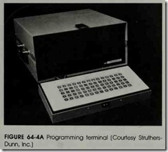
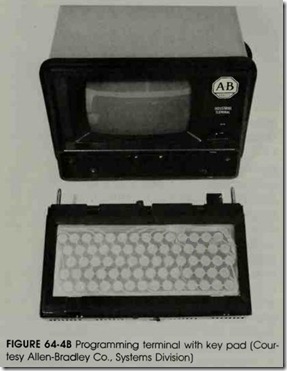
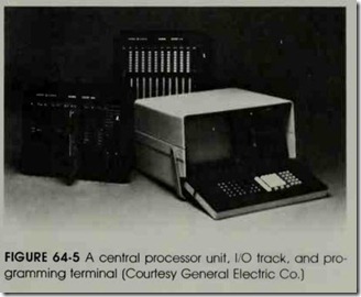
The other type of terminal uses a cathode ray tube, or CRT, to show the program. This terminal looks similar to a portable television set with a keyboard attached, figures 64-4A, 64-4B, and 64-5. It will display from four to six lines of the program at a time, depending on the manufacturer.
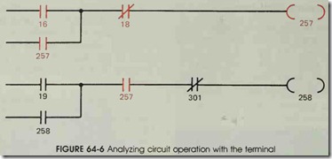
The terminal is not only used to program the controller, but it is also used to troubleshoot the circuit. When the terminal is connected to the CPU, the circuit can be examined while it is in operation. Figure 64-6 illustrates a circuit typical of those which are seen on the display. Notice that this schematic diagram is a little different from the typical ladder diagram. All of the line components are shown as normally open or normally closed contacts. There are no NEMA symbols for push buttons, float switches, limit switches;etc. The programmable controller recognizes only open or closed contacts. It does not know if a contact is controlled by a push button, a limit switch, or a float switch. Each contact, however, does have a number. The number is used to distinguish one contact from another.
The coil symbols look like a set of parenthe ses instead of a circle as shown on most ladder diagrams. Each line ends with a coil, and each coil has a number. When a contact symbol has the same number as a coil, it means the contact is con trolled by that coil. Figure 64-6 shows a coil num bered 257, and two contacts numbered 257. When relay coil 257 is energized, the controller inter prets both of these contacts to be closed.
Notice that the 257 contacts, contacts 16 and 18, and coil 257 are drawn with dark heavy lines. When a contact has a complete circuit through it, or a coil is energized, the terminal will illuminate that contact or coil. Contact 16 is illuminated, which means that it is closed and providing a cur rent path. Contact 18 is closed, providing a cur rent path to coil 257. Since coil 257 is energized, both 257 contacts are closed and providing current paths.
Contacts 19, 258, and 301 are not illumi nated. This means that contacts 19 and 258 are de energized and open. Contact 301, however, has been energized. This contact is shown as normally closed. Since it is not illuminated, it is open and no current path exists through it. Notice that the illumination of a contact does not mean that the contact has energized or changed position; it means that there is a complete path for current flow.
When the terminal is used to load a program into the central processing unit, contact and coil symbols on the keyboard are used. These symbol keys are used to load a ladder diagram similar to the one shown in figure 64-6 into the CPU. Pro gramming will be discussed in Unit 65.
The 1/0 Track
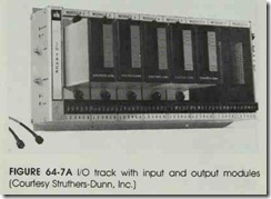
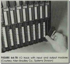
The I/0 track is used to connect the central processing unit to the outside world. It contains input modules which carry information to the CPU, and output modules which carry informa tion from the CPU. An I/0 track with input and output modules is shown in figures 64-7A and B. Most modules contain more than one input or out put. Any number from two to eight is common depending on the manufacturer. The modules shown in figure 64-7A can each handle four con nections. This means that each input module can handle four different inputs from pilot devices such as push buttons, float switches, or limit switches. Each output module can control four ex ternal devices such as pilot lights, solenoids, or motor starter coils. The operating voltage of mod ules can be alternating current or direct current and are generally either 120 or 24 volts. The I/0 track in figure 64-7A can handle eight modules. Since each module can accommodate four devices, this I/0 track can control 32 inputs or outputs.
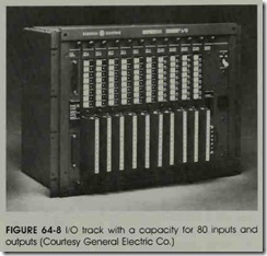
1/0 Capacity One factor which determines the size and cost of a programmable controller is its I/0 capacity. Many small units are designed to handle only 32 inputs or outputs. Large units can handle several hundred. The controller shown in figure 64-2A is designed to handle eight I/0 tracks. Since each I/0 track has 32 inputs or out puts, the controller has an I/0 capacity of 256. The I/0 track in figure 64-8 has a capacity for 80 inputs and outputs.
The Input Module The central processing unit of a programmable controller is extremely sensitive to voltage spikes and electrical noise. For this reason the input I/0 uses opto-isolation to electrically separate the incoming signal from the CPU. Another job performed by the input I/0 is debouncing any switch contacts connected to it.
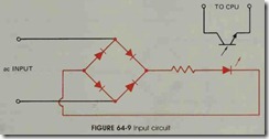
Figure 64-9 shows a typical circuit used for the input. The bridge rectifier changes the ac volt age into de voltage. A resistor is used to limit cur rent to the light-emitting diode. When the LED
turns on, the light is detected by the phototransis tor which signals the CPU that there is a voltage present at the input terminal.
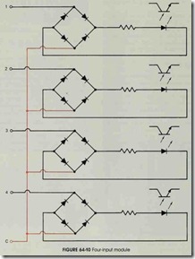
When the module has more than one input, the bridge rectifiers are connected together on one side to form a common terminal. On the other side the rectifiers are labeled 1, 2, 3, and 4. Figure 64-10 shows four bridge rectifiers connected to gether to form a common terminal.
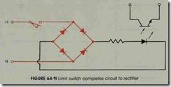
Figure 64-11 shows a limit switch connected to the input. Notice that the limit switch com pletes a circuit from the ac line to the bridge rec tifier. When the limit switch closes, 120-volts ac is applied to the rectifier causing the LED to turn on.
The Output Module The output module is used to connect the central processing unit to the load. The output is an opto-isolated, solid-state re lay. The current rating can range from .5 to 3 amps depending on the manufacturer. Voltage rat ings are generally 24 or 120 volts and can be ac or dc.
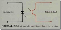
If the output is designed to control a de volt age, a power transistor is used to control the load, figure 64-12. The transistor is a phototransistor which is operated by a light-emitting diode. The LED is operated by the CPU.
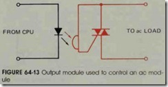
If the output is designed to control an ac load, a triac, rather than a power transistor, is used as the control device, figure 64-13. A photo detector connected to the gate of the triac is used to control the output. When the LED is turned on by the CPU, the photodetector permits current to flow through the gate of the triac and turn it on.
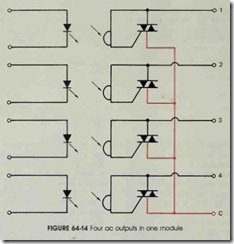
If more than one output is contained in a module, the control devices are connected to gether on one side to form a common terminal. Figure 64-14 shows an output module that con tains four outputs. Notice that one side of each triac has been connected to form a common ter minal. On the other side the triacs are labeled 1, 2, 3, and 4. If power transistors are used as the control devices, the emitters or the collectors can be connected to form a common terminal.
Figure 64-15 shows a solenoid coil connected to an ac output module. Notice that the triac is used as a switch to complete a circuit so that cur rent can flow through the coil. The output module does not provide power to operate the load. The power must be provided by an external power source. The amount of current an output can con trol is limited. Small current loads, such as sole noid coils and pilot lights, can be controlled di rectly by the I/0 output, but large current loads, such as motors, can not. When a large amount of current must be controlled, the output is used to operate the coil of a motor starter or contactor which can be used to control almost anything.
INTERNAL RELAYS
The actual logic of the control circuit is per formed by internal relays. An internal relay is an imaginary device that exists only in the logic of the computer. It can have any number of contacts, from one to several hundred, and the contacts can be normally open or normally closed. Internal re lays can be programmed into the computer by as signing a coil some number greater than the 110 capacity. For example, assume that the pro grammable controller has an 110 capacity of 256. If a coil is programmed into the computer and as signed a number greater than 256, 257 for in stance, it is an internal relay. Any number of con tacts can be controlled by relay 257 by inserting a contact symbol in the program and numbering it 257. If a coil is numbered 256 or less, it can turn on an output when energized.
Inputs are programmed in a similar manner. If a contact is inserted in the program and as signed the number 256 or less, the contact will be changed when a voltage is sensed at that input point. For example, assume that a normally open contact has been programmed into the circuit and assigned number 22. When voltage is applied to input number 22, the contact will close. Since 22 is used as an input in this circuit, care must be taken not to assign number 22 to a coil. Terminal number 22 cannot be used as both an input and an output at the same time.
Counters and Timers
The internal relays of a programmable con troller can be used as counters and timers. When timers are used, most of them are programmed in second time intervals. For example, assume that a timer is to be used to provide a delay of 10 seconds. When the delay time is assigned to the timer, the number 00100 is used. This means the timer has been set for 100 tenths of a second which is 10 seconds.
Off-Delay Circuit
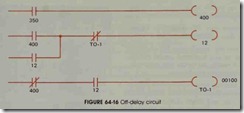
The internal timers of a programmable con troller function as on-delay relays. A simple circuit can be used, however, to change the sense of the on-delay timer to make it perform as an off-delay timer. Figure 64-16 is this type of circuit. The de sired operation of the circuit is as follows. When contact 350 closes, relay coil 12 energizes imme diately and turns on a solenoid valve. When con tact 350 opens, coil 12 remains energized for 10 seconds before it de-energizes and turns off the so lenoid.
This logic is accomplished as follows:
A. When contact 350 closes, internal relay 400 energizes.
B. When coil 400 energizes, normally open contact 400 closes and completes a circuit to coil 12, and normally closed contact 400 connected in series with timer T0-1 opens.
C. When relay coil 12 energizes, both normally open 12 contacts close, and the 110 output at terminal 12 connects the solenoid coil to the power line.
A. When contact 350 opens, internal relay 400 de-energizes.
B. This causes both 400 contacts to change back to their original positions.
C. When normally open contact 400 returns to its open state, a continued current path to coil 12 is maintained by the now closed con tact 12 connected parallel to it.
D. When normally closed contact 400 returns to its closed position, a circuit is completed through the now closed contact 12 to coil TO-I.
E. When coil T0-1 energizes, a 10-second timer starts. At the end of this time pe riod, contact T0-1 opens and de-energizes coil 12.
I. When coil 12 de-energizes, both 12 contacts return to the open position and the I/0 out put turns the solenoid off.
J. Timer T0-1 de-energizes when contact 12 opens and the circuit is back in its original start condition. ·
The number of internal relays and timers contained in a programmable controller is deter mined by the memory capacity of the computer. As a general rule, PCs that have a large I/0 capac ity will have a large memory, and machines that have less I/0 capacity will have less memory.
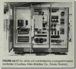
The use of programmable controllers has steadily increased since their invention in the late 1960s. A PC can replace hundreds of relays and occupy only a fraction of the space. The circuit logic can be changed easily and quickly without requiring extensive hand rewiring. They have no moving parts or contacts to wear out, and their down time is less than an equivalent relay circuit. A programmable controller used to control a de drive unit is shown in figure 64-17.
The programming methods presented in this text are for one type of programmable controller. Although there are about as many different meth ods of programming a programmable controller as there are manufacturers, the concepts presented here are basic to all controllers. It will be neces sary, however, to consult the instruction manual when using a particular brand of controller.
REVIEW QUESTIONS
1. What industry first started using programmable controllers?
2. Name two differences between PCs and home or business computers.
3. Name the four basic sections of a programmable controller.
4. In what section of the programmable controller is the actual circuit logic performed?
5. What device is used to program the PC?
6. What device separates the programmable controller from .the outside circuits?
7. What two functions are performed by an input 110?
8. If an output 110 controls de voltage, what electronic device controls the circuit?
9. If an output 110 controls ac voltage, what electronic device controls the circuit?
10. What is an internal relay?
