circuit–protection Devices
To protect the load from failure of the power supply, an over-voltage protection circuit t is used.
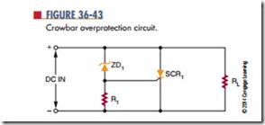
Figure 36-43 shows an over-voltage protection circuit called a crowbar. The SCR, placed in parallel with the load, is normally cut off (not conducting). If the output voltage rises above a predetermined level, the SCR turns on and places a short circuit across the load. With the short circuit across the load, very little current flows through the load. This fully protects the load. The short circuit across the load does not protect the power supply. The output of the power supply is shorted, thereby blowing the fuse of the power supply.
The zener diode establishes the voltage level at which the SCR turns on. It protects the load from voltage above the zener voltage. As long as the supply voltage is less than the zener diode voltage rating, the diode does not conduct. This keeps the SCR turned off.
If the supply voltage rises above the zener voltage due to a malfunction, the zener diode conducts. This creates a gate current to the SCR, turning it on and shorting out
the load. It should be noted that the SCR must be large enough to handle the large short-circuit current.
To protect circuits against excessive transient volt- age, a varistor is used. A varistor is an electronic component; the most common type is a metal-oxide varistor (moV). A MOV protects various types of electronic devices and semiconductor elements from switching and induced lightning surges. When ex- posed to high transient voltage, the MOV clamps the voltage to a safe level. An MOV absorbs potentially destructive energy and dissipates it as heat, protecting the circuit components.
MOV devices are made primarily of zinc oxide with small amounts of bismuth, cobalt, manganese, and other metal oxides. They can be connected in parallel for increased energy-handling capabilities. They can also be connected in series to provide higher volt- age ratings or to provide voltage ratings between the standard increments.
MOVs are available with peak current ratings ranging from 40 A to 70,000 A.
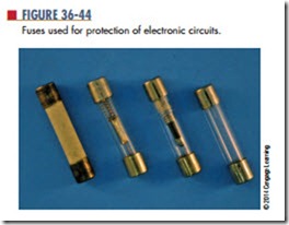
Another protection device is a fuse (Figure 36-44). A fuse is a device that fails when an overload occurs. A fuse is essentially a small piece of wire between two metal terminals. A hollow glass cylinder holds the metal terminals apart and protects the wire. Typically, a fuse is placed in series with the primary of the power supply transformer. If a large current flows in the power supply, it causes the fuse wire to overheat and melt. This opens the circuit so that no more current can flow. The glass housing of the fuse allows a visual check to see whether the fuse is blown.
Fuses are classified as normal or slow blow. A normal fuse opens as soon as its current is exceeded. In some circuits this is an advantage because it removes the overload very quickly. A slow-blow fuse
can withstand a brief period of overloading before it blows. This brief period of overloading occurs because the fuse wire heats more slowly. If the overload is present for longer than a few seconds, it blows the fuse. A slow-blow fuse may contain a spring for pulling the fuse wire apart once it melts. Some circuits can with- stand a surge in current. In these, a slow-blow fuse is preferable to a normal fuse.
The fuse is always installed after the switch on the “hot” (live and energized) lead of the AC power source. This disconnects the transformer from the AC power source when the fuse blows. By installing it after the switch, power can be removed from the fuse holder for added safety in replacing a blown fuse.
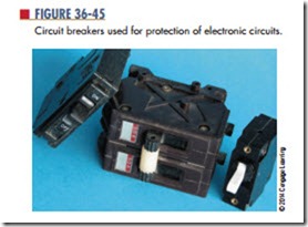
A disadvantage of the fuse is that it must be replaced each time it blows. A circuit breaker per- forms the same job but does not have to be replaced each time an overload occurs. Instead, the circuit breaker can be manually reset after the overload occurs (Figure 36-45). Circuit breakers are connected into the circuit in the same manner as fuses.
Questions
1. How does a crowbar over-voltage protection circuit operate?
2. How does a fuse operate when used in a circuit?
3. What are the different types of fuses?
4. Where is the fuse of any circuit-protection device located in a circuit?
5. What is the advantage of a circuit breaker over a fuse?


