INVERTERS
The static frequency conversion is the most rapidly growing area in modern electronics. It involves the conversion of ac power at one frequency to ac power at another frequency by using solid-state electronics. The traditional approaches to static ac frequency conversion employ the cycloconverter and the rectifier-inverter.
The cycloconverter is a device that directly converts ac power at one frequency to ac power at another frequency. The rectifier-inverter converts ac power to dc power and then converts dc power to ac power at a different frequency. A rectifier-inverter is divided into two components:
1. A rectifier to produce the dc power
2. An inverter to produce ac power from dc power
The Rectifier
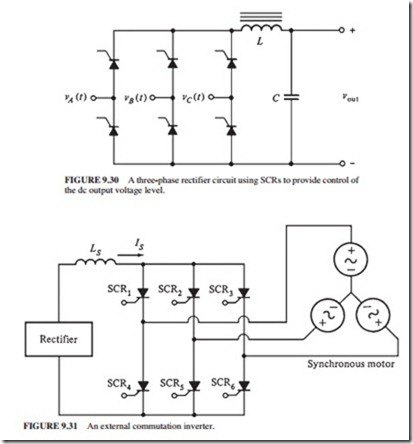
The basic rectifier described earlier used diodes. These devices have a problem when they are used for motor control. Their output voltage is fixed for a given input voltage. This problem can be overcome by replacing the diodes with SCRs (Fig. 9.30). The average dc output voltage of this rectifier depends on when the SCRs are triggered during the positive half-cycle. If they are triggered at the beginning of the half-cycle, this circuit will be the same as the rectifier with diodes. The output voltage will be 0 V if the SCRs are never triggered. The dc output voltage will be between 0 V and the maximum for any other firing angle between 0° and 180°.
The output voltage of this circuit will have more harmonic content than a simple rectifier due to using SCRs. An inductor and a capacitor are placed at the output of the rectifier to assist in smoothing the dc output.
External Commutation Inverters
The two commutation techniques used for inverters are external commutation and self- commutation. External commutation inverters require energy from an external motor or power supply to turn off the SCRs (Fig. 9.31). A three-phase synchronous motor is con- nected to the inverter to provide the countervoltage needed to turn off one SCR when its companions are fired.
The SCRs are triggered in this order: SCR1, SCR6, SCR2, SCR4, SCR3, SCR5. When SCR1 fires, the internal generated voltage in the synchronous motor provides the voltage needed to turn off SCR3.
Self-Commutated Inverters
A load cannot always guarantee the proper countervoltage for commutation. A self- commutation inverter must be used. It is an inverter in which the active SCRs are turned off by energy stored in a capacitor when another SCR is switched on. Self-commutation inverters are designed also using GTOs or power transistors. In these cases, commuta- tion capacitors are not required.
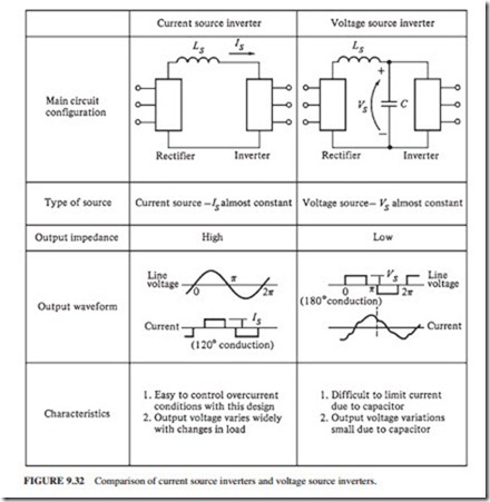
The types of self-commutation inverters are current source inverters (CSIs), voltage source inverters (VSIs), and pulse-width modulation (PWM) inverters. PWM inverters require faster switching components than CSIs and VSIs. Figure 9.32 shows a comparison between CSIs and VSIs.
The frequency of CSIs and VSIs is changed by changing the firing pulses on the gates of the SCRs. Both inverters can be used to drive ac motors at variable speeds.
Pulse-Width Modulation Inverters
Pulse-width modulation is the process of changing the width of pulses in a pulse train in direct proportion to a small control signal. The resulting pulses become wider when the control voltage is larger. A high-power waveform whose average voltage varies sinusoidally to drive ac motors can be generated by using a sinusoid at a desired frequency as the control voltage for a PWM circuit.
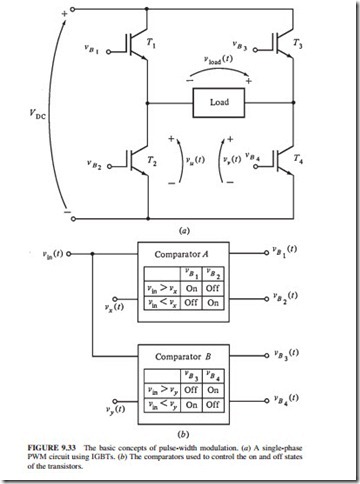
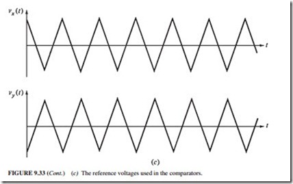
Figure 9.33 illustrates a single-phase PWM inverter circuit using IGBTs. The two comparators control the states of IGBT1 to IGBT4. A comparator compares the input voltage υin(t) to a reference signal. Based on the results of the test, it turns transistors on or off.
Comparator A compares υin(t) to the reference voltage υx(t). Based on the results of the comparison, it controls the IGBT’s T1 and T2.
Comparator B compares υin(t) to the reference voltage υy(t). It controls the IGBT’s T3 and T4 based on the results of the test. If υin(t) is greater than υx(t), then comparator A will turn on T1 and turn off T2, and vice versa.
If the control voltage is 0 V, then voltages υu(t) and υv(t) are identical. The load voltage out of the circuit υload(t) is zero (Fig. 9.34). If a constant positive control voltage equal to one-half of the peak reference voltage is applied, the resulting output voltage will be a train of pulses with a 50 percent duty cycle (Fig. 9.35).
Finally, if a sinusoidal control voltage is applied (Fig. 9.36), the width of the resulting pulse train varies sinusoidally with the control voltage. The output is a high-power wave- form whose average voltage is directly proportional to the average voltage of the control signal. The output waveform has the same fundamental frequency as the input control voltage. Evidently, there are harmonic components in the output voltage, but they do not usually have an effect in motor control applications. Additional heating may be generated in the motor due to harmonic components. However, this additional heating is compensated by using specially designed motors or by derating an ordinary motor.
A complete three-phase PWM inverter consists of three single-phase inverters with sinu- soids shifted by 120° between phases. The variation of the input control voltage frequency provides the frequency control in a PWM inverter.
During a single cycle of the output voltage, a PWM inverter switches state numerous times. The frequencies of the reference voltages can be as high as 12 kHz. The components in a PWM inverter must change state up to 24,000 times every second. Components faster than CSIs or VSIs are required for this rapid switching. High-power and high-frequency components such as GTO thyristors, IGBTs, and/or power transistors are used in PWM inverters. A microcomputer mounted on a circuit board within the PWM motor controller provides the control voltage to the comparator circuits. The microcomputer can vary the control voltage to obtain different frequencies and voltage levels.
