A RELAXATION OSCILLATOR USING A PNPN DIODE
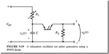
Figure 9.19 illustrates a relaxation oscillator or pulse-generating circuit built using a PNPN diode. The following conditions are assumed:
1. The power supply voltage VDC must exceed VBO for the PNPN diode.
2. VDC/R1 must be less than IH for the PNPN diode.
3. R1 must be much larger than R2.
When the switch in the circuit is closed, capacitor C will charge with a time constant
T = R1C. As the voltage increases, it will exceed VBO and the PNPN diode will turn on.
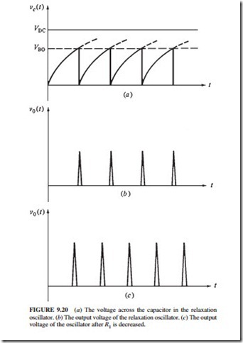
The capacitor will discharge through it. The PNPN diode will turn off. Figure 9.20a and b illustrate the voltage across the capacitor and the resulting output voltage and current.
The timing of the pulses can be changed by varying R1. If R1 is decreased, the capacitor will charge more quickly and the PNPN diode will be triggered sooner. The pulses will be closer together.
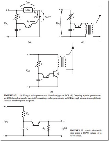
This circuit can be used to trigger an SCR by removing R2 and connecting the SCR gate lead in its place (Fig. 9.21a). The circuit can be coupled to the SCR through a transformer (Fig. 9.21b). The pulse can be amplified by an extra transistor stage if more gate current is needed to drive the SCR (Fig. 9.21c). The circuit can also be built using a DIAC instead of the PNPN diode (Fig. 9.22).


