Distance travelled
The sensing of distance travelled, as distinct from distance from a fixed reference point, can make use of a variety of sensors. In this case, we shall start with the sensors for short distance movements, because for motion over large distances the distance travelled will generally be calculated by comparing position measurements rather than directly. Sensors for small distances can make use of resistive, capacitive or inductive transducers in addition to the use of interferometers (see Chapter 1) and the millimetrewave radar methods that have been covered earlier. The methods that are described here are all applicable to distances in the range of a few millimetres to a few centimetres. Beyond this range the use of radar methods becomes much more attractive.
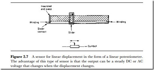
A simple system of distance sensing is the use of a linear (in the mechanical sense) potentiometer (Figure 2.7). The moving object is connected to the slider of the potentiometer, so that each position along the axis will correspond to a different output from the slider contact – either AC or DC can be used since only amplitude needs to be measured. The output can be displayed on a meter, converted to digital signals to operate a counter, or used in conjunction with voltage level sensing circuits to trigger some action when the object reaches some set position. The main objections to this potentiometric method are: that the range of movement is limited by the size of potentiometers that are available (although purpose-built potentiometers can be used), and that the friction of the potentiometer is an obstacle to the movement. The precision that can be obtained depends on how linear (in the electrical sense) the winding can be made, and 0.1% should be obtainable with reasonable ease.
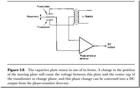
An alternative that is sometimes more attractive, but often less practical, is the use of a capacitive sensor. This can take the form of a metal plate located on the moving object and moving between two fixed plates that are electrically isolated from it. The type of circuit arrangement is illustrated in Figure 2.8, showing that the fixed plates are connected to a transformer winding so that AC signals in opposite phase can be applied. The signal at the moveable plate will then have a phase and amplitude that depends on its position, and this signal can be processed by a phase-sensitive detector to give a DC voltage that is proportional to the distance from one fixed plate. Because the capacitance between plates is inversely proportional to plate spacing, this method is practicable only for very short distances, and is at its most useful for distances of a millimetre or less.
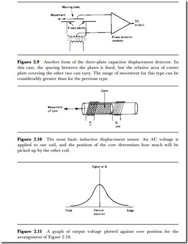
An alternative physical arrangement of the plates is shown in Figure 2.9, in which the spacing of the fixed plates relative to the moving plate is small and constant, but the movement of the moving plate alters the area that is common to the moving plate and a fixed plate. This method has the advantage that an insulator can be used between the moving plate and the fixed plates, and that the measurable distances can be greater, since the sensitivity depends on the plate areas rather than on variable spacing.
The most commonly used methods for sensing distance travelled on the small scale, however, depend on induction. The basic principle of induction methods is illustrated in Figure 2.10, in which two fixed coils enclose a moving ferromagnetic core. If one coil is supplied with an AC signal, then the amplitude and phase of a signal from the second coil depends on the position of the ferromagnetic core relative to the coils. The amplitude of signal, plotted against distance from one coil, varies as shown
in Figure 2.11, and the disadvantage of this simple arrangement is that a given amplitude other than the maximum can correspond to more than one distance. In addition, the shape of the graph means that even if the range is restricted the output is never linearly proportional to the distance.
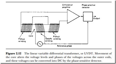
A development of the simple inductive sensor is the linear variable differen- tial transformer (LVDT), which is now the most commonly used sensor for distance in the range of millimetres to centimetres. The principle is illustrated by the circuit diagram shown in Figure 2.12. The device consists basically of three fixed coils, one of which is connected to an AC supply. The other two coils are connected to a phase-sensitive detector, and as a core of ferromagnetic material moves in the coil axis, the output from the detector will be proportional to the distance of the core from one end of the coils. As the name suggests, the output from the phase-sensitive detector will be fairly linearly proportional to distance, and there are considerable advantages as compared to other types of distance sensors, as follows.
1. Virtually zero friction, since the core need not be in contact with the coils, and so no wear.
2. Linear output.
3. Very high resolution, depending mainly on the detector.
4. Good electrical isolation between the core and the coils.
5. A large output signal from the coils so that the phase-sensitive detector needs little or no amplification.
6. No risk of damage if the core movement is excessive.
7. Strong construction that is resistant to shock and vibration.
Commercially available LVDTs can be used with either AC or DC supplies; the DC types use a miniature built-in oscillator inverter to provide the AC for the coils. The performance of the AC types is always superior, but in some systems where, because of lack of space, no separate AC supply can be provided, the DC type must be used. The AC supply is at a high frequency and for the AC type of LVDT it is supplied by a separate inverter system, and is available cased, on a plug-in card, or as a hybrid thick-film module.
Short-stroke LVDTs have a useful linear range of movement of a few millimetres only, from + 1 mm to ±5 mm depending on design and construction. The long-stroke type can provide a displacement range of as large as ± 62 mm. Typically, a frequency of 5 kHz is used for the AC drive. A miniature LVDT with ±3 mm stroke, type SM3, has body dimensions of only 9.52 mm diameter x 35 mm length, not including the plunger arm. The longer stroke versions are larger, with a body diameter of 25 mm and body length (excluding arm) of 150 mm for a ±25 mm stroke.
• Because of the seven advantages listed above, the LVDT has superseded most other types of distance sensors. For very small distances, the strain gauge (see Chapter 1) can be used; laser interferometers are applicable when very precise changes must be sensed, and radar methods are used for longer distances.
One peculiar advantage of the laser interferometer is that its output can readily be converted to digital form, since it is based on the counting of wavepeaks. Most sensors give analogue outputs, and where a sensor is described as having a digital output, this usually implies that an analogue to digital conversion has been carried out. The interferometer is one of the few sensors which is capable of providing a genuinely digital output. Another is the linear digital encoder, and since digital methods are of ever- increasing importance in measurement and control, a description of this device in detail is appropriate here.
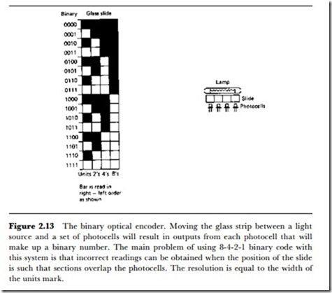
The linear digital encoder gives an output which is a binary number that can be proportional to the distance of the encoder relative to a fixed point. The encoder can, of course, be fixed with an object moving relative to it. The simplest form of encoder of this type is optical, and the principle is illustrated in Figure 2.13. A glass strip is printed with a pattern of the form shown, using large blocks rather than the more practical lines, alternately opaque and transparent. At one edge, the pattern is comparatively fine, and the size of each unit determines the resolution of the device – the smallest change of distance that can be sensed is the width of one block or bar. The next strip along contains blocks or bars of double the width of the first, again alternately opaque and transparent. The next strip in turn has bars that are twice the width of its predecessor and so on. The number of strips determines the number of binary digits in the output and the number of increments of position that can be detected. For example, if the pattern consists of four strips, then the maximum number of increments of position is 24 = 16 which is not likely to be of practical use except for specialized purposes. For eight strips, however, the number of resolvable positions is 28 = 256, and for 16 strips, the number is 65536.
The optical linear encoder is read by using a sensor for each strip or track. The usual scheme is to use a strip of photocells so that light from a source
on the other side of the encoder strip will pass through the transparent sections to the appropriate photocell. The output of each photocell will therefore, after amplification, be a 1 or a 0 signal, and the set of photocells provides a binary number if the cells are read in order of the broadest bars towards the finest. If an eight bit number is used, with eight strips and eight photocells, then the number range is 0 to 256, and this determines the resolution as being 1f256 of the total length of the encoder. For example, if the encoder is 10 cm long, then the resolution is 10f256 cm, or 0.39 mm. The device can be used with the light and photocells at rest and the encoder slide moving (the normal use), or with the encoder slide at rest and the light source andfor photocells moving. The photocells must be placed almost in contact with the encoder slide, and with suitable light shielding to ensure that stray light does not cause false responses.
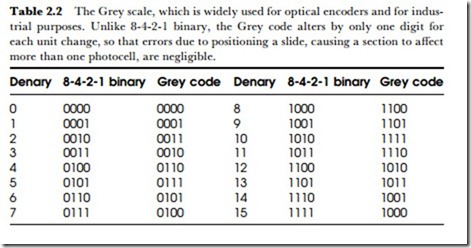
One problem that arises with optical linear (or angular) encoders is the suitability of the coding system. The usual binary number system is often termed 8-4-2-1 code, in recognition of the fact that each digit place represents a doubling or halving of the value of the adjacent place. This can mean that some changes of number can involve changes in more than one of the digits. For example, the change from 7 to 8 in binary terms is the
change from 0111 to 1000, in which each of four digits has changed simply to indicate a value change of just one unit.
For this reason, another code, the Grey code (illustrated in Table 2.2), is used to a much greater extent for devices such as optical encoders. In a Grey code scale, a change of one unit will affect only one digit of the binary number, so that the chances of error caused by misalignment of the sectors of the coding glass, or by half-way positions between sectors, are greatly reduced. ICs exist which will convert Grey code into normal 8-4-2- 1 binary, so that arithmetic can be carried out on the numbers if needed. For some applications, conversion may not be necessary.
The linear digital encoder systems provide a set of binary digital signals directly, but since this requires a slide which is very precisely printed and which will use one detector for each binary digit, less direct conversion methods are often used. A slide using only a single set of equally spaced markings can be used in conjunction with a two-phase pick-up system to provide pulse signals whose phasing can be used to indicate direction and whose count indicates distance moved. A system of this type has only a single output to a counter (with a second connection if direction is to be sensed), and the counter will then convert into binary code. This type of system is considered more fully under the heading of Rotation later in this chapter.
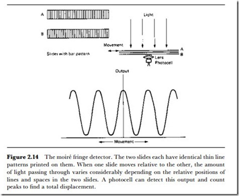
Another optical method that is particularly useful for small displacements, particularly vibration amplitudes, is the optical grating method whose principles are illustrated in Figure 2.14. Each grating consists of a glass or plastic plate on which fine lines are engraved. One grating is fixed and the other is part of the object whose movement is to be detected. As the object moves, the amount of light that passes through both gratings will be altered – ideally in the pattern of a sine wave for a movement that is of an amplitude equal to the distance between grating lines. This altera-
tion of the light amplitude, termed moire’ fringes, can be detected by a photocell and used to provide an electrical output. Large movements are read in terms of the number of complete waves of output from the photocell, small movements in terms of the amplitude of the signal.
