PNEUMATIC CONTROL SYSTEM EXAMPLE
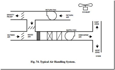
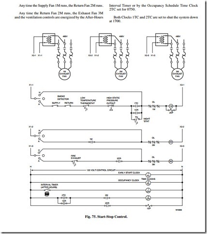
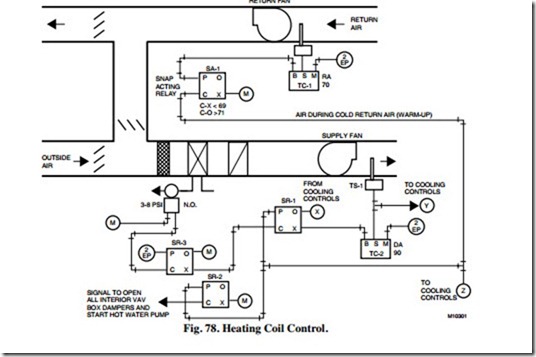
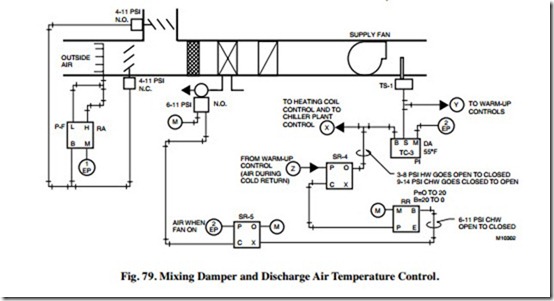
The following is an example of a typical air handling system (Fig. 74) with a pneumatic control system. The control system is presented in the following seven control sequences (Fig. 75 through 79):
— Start-Stop Control Sequence.
— Supply Fan Control Sequence.
— Return Fan Control Sequence.
— Warm-Up/Heating Coil Control Sequence.
— Mixing Damper Control Sequence.
— Discharge Air Temperature Control Sequence.
— Off/Failure Mode Control Sequence.
Controls are based upon the following system information and control requirements:
System Information:
— VAV air handling system.
— Return fan.
— 35,000 cfm.
— 4,000 cfm outside air.
— 3,000 cfm exhaust air.
— Variable speed drives.
— Hot water coil for morning warm-up and to prevent discharge air from getting too cold in winter .
— Chilled water coil.
— Fan powered perimeter VAV boxes with hot water reheat.
— Interior VAV boxes.
— Water-side economizer.
— 8:00 A.M to 5:00 P.M. normal occupancy.
— Some after-hour operation.
Control Requirements:
— Maintain design outside air airflow during all levels of supply fan loading during occupied periods.
— Use normally open two-way valves so system can heat or cool upon compressed air failure by manually running pumps and adjusting water temperatures.
— Provide exhaust/ventilation during after-hour occupied periods.
— Return fan sized for 35,000 cfm.
START-STOP CONTROL SEQUENCE
Fans 1M through 3M (Fig. 75) operate automatically subject to starter-mounted Hand-Off-Automatic Switches.
The Supply Fan 1M is started and controls are energized by Electric-Pneumatic Relay 2EP at 0645 by one of the following:
— An Early Start Time Clock 1TC
— A drop in perimeter space temperature to 65F at Night Thermostat TN
— An after-hour occupant setting the Spring-Wound
Interval Timer for 0 to 60 minutes.
The Supply Fan 1M operation is subject to manually reset safety devices including Supply and Return Air Smoke Detectors; a heating coil, leaving air, Low Temperature Thermostat; and a supply fan discharge, duct High Static Pressure Cut-Out.
Any time the Supply Fan 1M runs, the Return Fan 2M runs.
Any time the Return Fan 2M runs, the Exhaust Fan 3M and the ventilation controls are energized by the After-Hours Interval Timer or by the Occupancy Schedule Time Clock 2TC set for 0750.
Both Clocks 1TC and 2TC are set to shut the system down at 1700.
SUPPLY FAN CONTROL SEQUENCE
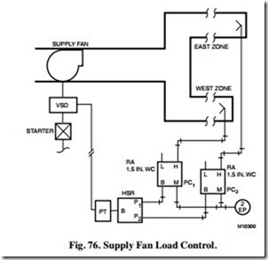
Any time the Supply Fan (Fig. 76) runs, the pressure controller with the greatest demand, Static Pressure Controller PC or PC , operates the Electronic-Pressure Transducer PT.
The controller used is determined by High Pressure Selector Relay HSR. Transducer PT controls the Supply Fan Variable Speed Drive (VSD) to maintain duct static pressure. The pick-up probes for Static Pressure Controllers PC and PC are located at the end of the east and west zone ducts.
RETURN FAN CONTROL SEQUENCE
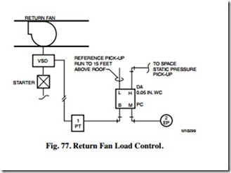
Static Pressure Controller PC (Fig. 77) controls the return fan variable speed drive to maintain space static pressure. The pick-up probe is located in the space
NOTE: 1. Because of varying exhaust between occupied and warm-up modes, space static pressure control of the return fan is selected. Return fan tracking from supply fan airflow is acceptable but is complex if varying exhaust is worked into the control scheme.
2. Exercise care in selecting location of the inside pick-up and in selection of the pressure controller.
Location of the reference pick-up above the roof is recommended by ASHRAE.
3. To prevent unnecessary hunting by the return fan at start-up, the supply fan control signal should be slow loading such that the supply fan goes from zero or a minimum to maximum load over three minutes. Shut down should not be restricted.
WARM-UP/HEATING COIL CONTROL SEQUENCE
Any time the Supply Fan (Fig. 78) runs and the return air temperature is below 69F, Temperature Controller TC-1 trips Snap-Acting Relay SA-1 to position Switching Relays SR-1 and SR-2 to initialize warm-up control. Relay SA-1 also positions Switching Relay SR-4 to disable cooling controls. Switching Relay SR-2 opens all interior VAV box dampers and starts the hot water pump. Relay SR-1 switches the hot water valve from normal control to warm-up control via Controller TC-2 and modulates the hot water valve to maintain a discharge air temperature setpoint of 90F.
NOTE: Fan powered perimeter VAV boxes are cool in this mode and operate with the fans on and at the minimum airflow (warm air) setpoints. Reheat valves at each box operate as needed. This allows the warm-up cycle to operate the air handling unit (AHU) fans at a reduced and low cost power range.
MIXING DAMPER CONTROL SEQUENCE
Any time the AHU (Fig. 79) runs in the occupied mode with Electric-Pneumatic Relay 1EP energized, Outside Air airflow Controller P-F modulates the outside air damper toward open and the return air damper toward closed (or vice versa) in unison to maintain design outside air at 4000 cfm.
NOTE: These dampers can control in sequence also, but unison control positions the damper blades better for mixing which is helpful during freezing periods. If the outside air is provided from an outside air shaft with an outside air fan, an outside air filter is helpful to keep the flow sensing element/pick-up clean and effective. Electric-Pneumatic Relay 1EP starts the outside air system.
DISCHARGE AIR TEMPERATURE CONTROL SEQUENCE
Any time the AHU (Fig. 79) operates in the non-warm-up mode, Switching Relay SR-4 operates to allow the normal Discharge Air Temperature Controller TC-3 to modulate the hot water valve closed (through Switching Relay SR-1, Fig. 77) and the chilled water valve open in sequence, on a rising cooling load, to maintain the Temperature Controller TC-3 setpoint. Controller TC-3 is a PI (proportional plus integral) controller.
NOTE: In this constant 4000 cfm outside air system, if the return air is 72F and the outside air is -5F, the mixed air temperature will drop below 55F if the AHU airflow drops below 52 percent of the design airflow.
OFF/FAILURE MODE CONTROL SEQUENCE
If compressed air fails, both control valves open, the outside air damper closes, and the return air damper opens.
When the fan is off, Switching Relay SR-3 (Fig. 78) positions to close the hot water valve, Switching Relay SR-5 (Fig. 79) positions to close the chilled water valve, the outside air damper closes, and the return air damper opens.
