oscilloscopes
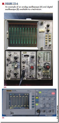
An oscilloscope is the most versatile piece of test equipment available for working on electronic equipment and circuits. It provides a visual display of what is occurring in the circuit. Figure 22-6A shows an analog oscilloscope, and Figure 22-6B shows a digital oscilloscope. Both the analog and the digital oscilloscopes perform the same functions.
An oscilloscope is capable of providing the follow- ing information about an electronic circuit:
1. The frequency of a signal
2. The duration of a signal
3. The phase relationship between signal waveforms
4. The shape of a signal’s waveform
5. The amplitude of a signal
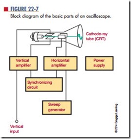
The basic parts of an analog oscilloscope are a cathode-ray tube (Crt), a sweep generator, horizontal and vertical deflection amplifiers along with their synchronizing circuits, and power supplies (Figure 22-7).
The sweep generator provides a sawtooth waveform as input to the horizontal deflection amplifier. The horizontal and vertical deflection amplifiers increase the amplitude of the input voltage to the proper level for deflection of the electron beam in the cathode-ray tube. The power supply provides DC voltages to operate the amplifiers and cathode-ray tube.
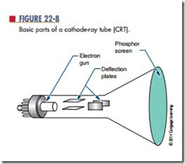
The cathode-ray tube consists of three parts: a phosphor screen, deflection plates, and an electron gun (Figure 22-8). The phosphor screen emits light when struck by electrons. The electron gun generates the electron beam that strikes the screen. As the electron beam approaches the screen, the deflection plates change the direction of the electron beam as it approaches the screen. The horizontal deflection plate is attached to the sweep generator, which moves the
electron beam back and forth across the screen. The vertical amplifier is connected to the input signal and controls its amplitude.
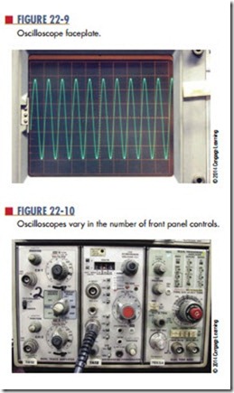
Using a faceplate that has been marked in cen- timeters along both a vertical and a horizontal axis (Figure 22-9), the oscilloscope can be calibrated with a known voltage before testing an unknown signal. Then, when the unknown signal is applied, its amplitude can be calculated. Rather than mark the actual faceplate of the CRT, oscilloscopes are provided with separate faceplates called graticules that are mounted in front of the CRT.
The power switch of an oscilloscope is usually located on the front panel (Figure 22-10). It may be a toggle, push-button, or rotary switch, and may be mounted separately or mounted with another switch. Its purpose is to apply line voltage to operate the oscilloscope.
The intensity (also called brightness) switch is used to control the electron beam within the CRT. It is a rotary control and allows the operator to adjust the electron beam for proper viewing.
C A u t i o n !
Keep the brightness as low as possible. Too much intensity for too long a time can burn a hole or etch a line in the phosphor screen, ruining the CRT.
The focus and astigmatism controls are connected to the electron gun and are used to adjust the electron beam size and shape before it reaches the deflection plates. Both of these controls are rotary controls. To use them, the electron beam is slowly swept across the
screen of the CRT, and both controls are alternately adjusted until a perfectly round dot is obtained. On some newer oscilloscopes, the astigmatism control may be recessed below the front panel.
The horizontal and vertical position controls are also rotary controls, and they allow the electron beam to be positioned anywhere on the face of the CRT. Initially, they are set so that the electron beam sweeps across the center of the CRT. They are then adjusted to place the electron beam in a position to measure amplitude and time by its placement on a graticule.
The vertical block consists of a vertical input jack, an AC/DC switch, and a volts/cm rotary switch. The oscilloscope probe is connected to the input jack. The probe is then connected to the circuit to be tested. The AC/DC switch allows the signal to be sent directly to the vertical amplifier in the DC position or to a capacitor in the AC position. The capacitor in the AC position is used to block any DC component on the signal being checked. The volts/cm switch is used to adjust the amplitude of the input signal. If the signal is too large, the vertical amplifier distorts it; if the signal is too small, it is amplified. This control is calibrated to match the CRT faceplate. Where this control is set depends on the amplitude of the signal on the CRT.
The horizontal block, also referred to as the time base, consists of a time/cm rotary switch, a trigger-control switch, and a triggering level control. The time/cm switch sets the horizontal sweep rate that is to be represented by the horizontal graduations. The lower the setting, the fewer cycles per second are displayed. The trigger control switch selects the source and polarity of the trigger signal. The trigger source can be line, internal, or external. The polarity can be positive or negative. When line is selected as the trigger source, the power-line frequency of 60 hertz is used as the trigger frequency. When internal (INT) is selected as the trigger frequency, the input signal frequency is used as the trigger frequency. External (EXT) allows a trigger frequency from an external source to be used.
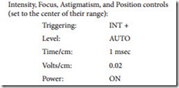
The level control sets the amplitude that the trig- gering signal must exceed before the sweep genera- tor starts. If the level control is in the AUTO position, the oscilloscope is free running. Turning the level con- trol results in a blank screen when no signal is present. The level control is turned to a point where the trace on the oscilloscope goes out, and then it is turned back to where the trace reappears. At this point, a stable presen- tation is on the screen. By using the triggering and level controls together to synchronize the sweep generator with the input signal, a stable trace can be obtained on the CRT. Before use, the oscilloscope should be checked to determine that it is not faulty. Misadjusted controls can give false readings. Most oscilloscopes have a built-in test signal for setup. Initially the controls should be set
in the following positions:
Intensity, Focus, Astigmatism, and Position controls (set to the center of their range):
The oscilloscope probe should be connected to the test jack of the voltage calibrator. A square wave should
appear on the trace of the CRT. The display should be stable and show several cycles at the amplitude indicated by the voltage calibrator. The oscilloscope can now be used.
To use the oscilloscope, set the volts/cm selector switch to its highest setting. Connect the input signal to be observed, and rotate the volts/cm selector switch until the display is approximately two-thirds of the screen’s height. Adjust the time-base controls to produce a stable trace and to select the desired number of cycles.
Questions
1. What can be learned about a waveform by using an oscilloscope?
2. What are the basic parts of an oscilloscope?
3. Describe a basic procedure for setting up an oscilloscope before its initial use.
4. What are applications of an oscilloscope when working with a circuit?
5. What does the graticule marked on the screen of the oscilloscope represent?
