Unusual measurements
Laboratory work, whether comparatively routine in nature or involving new ideas, often requires sensing and measuring systems that have not been covered by any of the examples up to this point. In many cases, this does not imply that completely new sensors have to be developed, because an unusual application can often be catered for by using a combination of existing sensors. Research laboratories, however, generally have to construct their own sensing and measuring systems because the nature of the work implies that nothing is available. In this chapter, we shall consider some types of sensors and measuring methods that are used in laboratory work, in engineering development and in some types of geological work, but which find little or no application outside these uses.
Permittivity
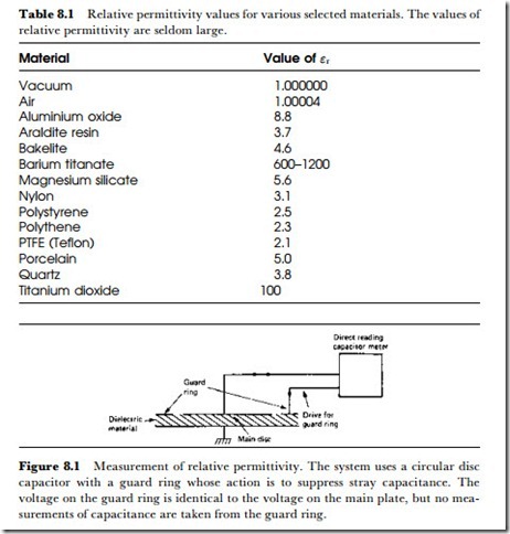
The permittivity of an insulating material determines its effect on the capacitance of a pair of conducting plates that sandwich the material. The usual measurement of permittivity is as relative permittivity, symbol cr, meaning the permittivity of the materials divided by the permittivity of space (a vacuum). This quantity was formerly known as dielectric constant. The permittivity of a vacuum is close enough to the permittivity of air to allow this amount to be used except for the most precise measurements. The measure- ment can be for the purpose of determining how effective a new material (usually a plastic or ceramic material) would be when used as a dielectric for capacitors, but it can also be used in assisting to determine the structure of a material. Table 8.1 shows permittivity values for some common materials.
The outline of a system for measuring relative permittivity is shown in Figure 8.1. The parallel-plate capacitor is constructed with circular plates and a ‘guard-ring’ to offset the effects of stray capacitance at the edge. The value of capacitance is measured (using a capacitance meter) with, and then without, the dielectric, maintaining the same spacing between the plates. The ratio of capacitance values is taken as the relative permittivity of the material.
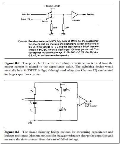
The principle of the capacitance meter is shown in Figure 8.2. The capacitor is alternately charged from a constant-voltage source and dis- charged through a meter or into an integrating counter. The switching is carried out by a MOS array, and for high sensitivity has to be done at a high frequency, e.g. several MHz. The capacitance is obtained as shown in the example from a reading of current, and the whole system can be made direct-reading.
In addition to the relative permittivity of a capacitor dielectric, its loss Jactor may have to be assessed. This is a very much more difficult measure- ment unless the loss factor is large, although for some purposes (such as soil sample analysis) large loss factors are normal. The measuring method that is used is a bridge in which the capacitor with the dielectric under test is balanced against a standard low-loss capacitor and a phase-shift resistor, using the circuit of Figure 8.3, the Schering bridge, or a more specialized type.
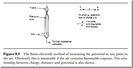
Electrostatic charge sometimes has to be measured by electronic methods, and the simplest method is to measure the potential at various distances
from the charge- the relationship between potential and charge is shown in Figure 8.4. The ‘connection’ between the voltmeter and the air is established by using a flame to ionize the air around the detector. The voltmeter must have a very high input impedance, and a MOS type is normally used to replace the older valve voltmeters that were once common in measuring laboratories. Two determinations of potential at different distances are usually needed to establish the amount of charge, although this method will not be suitable if the charge leaks away rapidly. Note that there is no electrical connection between the charged object and the voltmeter; the potential is due to the field set up by the charge.


