nonsinusoidal oscillators
nonsinusoidal oscillators are oscillators that do not produce a sine-wave output. There is no specific nonsinusoidal waveshape. The nonsinusoidal oscillator output may be a square, sawtooth, rectangular, or triangular waveform or a combination of two wave- forms. A common characteristic of all nonsinusoidal oscillators is that they are a form of relaxation oscillator. A relaxation oscillator stores energy in a reactive component during one phase of the oscillation cycle and gradually releases the energy during the relaxation phase of the cycle.
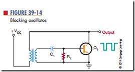
Blocking oscillators and multivibrators are relaxation oscillators. Figure 39-14 shows a blocking oscillator circuit. The reason for the name is that the transistor is easily driven into the blocking (cutoff ) mode. The blocking condition is determined by the discharge from capacitor C1. Capacitor C1 is charged
through the emitter-base junction of transistor Q1.
However, once capacitor C1 is charged, the only discharge path is through resistor R1. The RC time constant of resistor R1 and capacitor C1 determines how long the transistor is blocked, or cut off, and also determines the oscillator frequency. A long time constant produces a low frequency; a short time constant produces a high frequency.
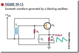
If the output is taken from an RC network in the emitter circuit of the transistor, the output is a saw- tooth waveshape (Figure 39-15). The RC network determines the frequency of oscillation and produces the sawtooth output. Transistor Q1 is forward biased
by resistor R1. As transistor Q1 conducts, capacitor C1 charges quickly. The positive potential on the top plate of capacitor C1 reverse biases the emitter junction, turning off transistor Q1. Capacitor C1 discharges through resistor R2, producing the trailing portion of the sawtooth output. When capacitor C1 discharges, transistor Q1 is again forward biased and conducts, repeating the action.
Capacitor C1 and resistor R2 determine the fre- quency of oscillation. By making resistor R2 variable, the frequency can be adjusted. If resistor R2 offers high resistance, a long RC time constant results, producing a low frequency of oscillation. If resistor R2 offers low resistance, a short RC time constant results, producing a high frequency of oscillation.
A multivibrator is a relaxation oscillator that can function in either of two temporarily stable conditions and is capable of rapidly switching from one temporary state to the other.
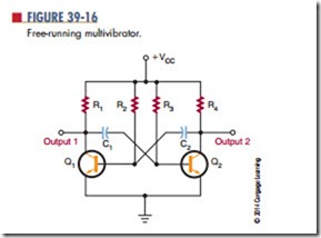
Figure 39-16 shows a basic free-running multivibrator circuit. It is basically an oscillator consisting of two stages coupled so that the input signal to each stage is taken from the output of the other. One stage conducts while the other stage is cut off, until a point is reached where the stages reverse their conditions. The circuit is free-running because of regenerative feedback.
The coupling circuit determines the frequency of oscillation.
An astable multivibrator is one type of free- running multivibrator. The output of an astable multivibrator is rectangular. By varying the RC time constants of the coupling circuits, rectangular pulses of any desired width can be obtained. By changing the values of the resistor and capacitor, the operating frequency can be changed. The frequency stability
of the multivibrator is better than that of the typical blocking oscillator.
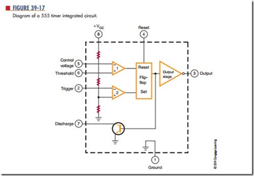
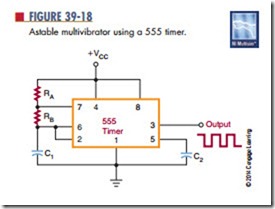
An integrated circuit that can be used as an astable multivibrator is the 555 timer (Figure 39-17). This integrated circuit can perform many functions. It con- sists of two comparators, a flip-flop, an output stage, and a discharge transistor. Figure 39-18 shows a schematic diagram in which the 555 timer is used as an astable multivibrator. The output frequency is deter- mined by resistors RA and RB and capacitor C1. This circuit finds wide application in industry.
Questions
1. Draw the more commonly used nonsinusoidal waveforms.
2. What is a relaxation oscillator?
3. Give two examples of relaxation oscillators.
4. Draw a schematic diagram of a blocking oscillator.
5. Draw a schematic diagram of a 555 timer used as an astable multivibrator.
