STARTING
The condition at the starting of a motor is similar to that of a transformer with a short-circuited secondary, since the rotor, by con struction, is being short-circuited by means of heavy metal bars, as previously described.
When the rated voltage is applied to the stator windings of a squirrel-cage motor, a heavy current is drawn from the line. It ranges from four to seven times the full-load current, depending on the type of motor. This high current is momentary only, and falls off rapidly as the motor increases its speed. The magnitude of this current depends on the electrical design of the motor and is independent of the mechanical load. The duration of the starting current, however, depends on the time required for acceleration, which in turn depends on the nature of the driven load.
Squirrel-cage motors in industrial plants are usually started by one of the following methods:
1. Directly across the line,
2. By autotransformers (compensators),
3. By resistance in series with the stator winding,
4. By means of a step-down transformer.
Squirrel-cage motors of 5 hp (3.73 kW) or less are generally started with line switches, connecting them directly across the line. The switches are usually equipped with thermal devices which open the circuit when overloads are carried beyond predetermined limits. Large motors usually require various voltage-reducing methods of the type previously mentioned.
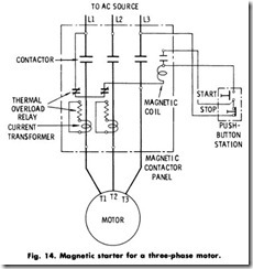
All types of squirrel-cage motors may be thrown directly across the line-provided, of course, that the starting currents do not cause voltage fluctuations that will interfere with power service elsewhere, and also that the starting currents do not exceed those permitted by local power regulations. VJhen so started, a magnetic contactor is usually employed, operated from a start-stop push-button station, or automatically from a float switch, thermostat, pressure regulator, or other pilot-circuit control device.
Across-The-Line Starting
There are several across-the-line starting methods whose use depends on the duty of the motor and the method of control desired. It is customary to employ a straight single-throw switch or contactor for motors up to 5 hp, (3.73 kW), with fuses rated for the starting current.
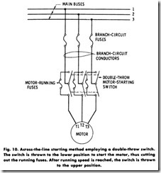
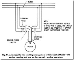
The methods of starting shown in Figs. 10 and 11 require two sets of fuses and a double-throw switch. The high-current fuses are used for starting only, while the running fuses have a lower current rating. These methods of starting are used for motors up to 250 volts.
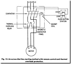
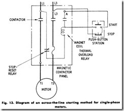
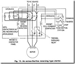
With large motors having a voltage rating of from 440 to 600 volts, oil circuit breakers or magnetic switches are generally used. Both the oil circuit breakers and magnetic switches are provided with overload and undervoltage protection. Various types of across-the-line starters used with squirrel-cage motors are shown in Figs. 12 to 15.
Autotransformer Starting
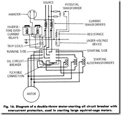
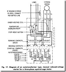
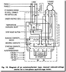
The autotransformer, or compensator, method of starting employs two or three autotransformers for the reduction of voltage to the motor terminal. The autotransformer type of starter has the advantage of drawing less current from the line for a given reduction in voltage to the motor terminals. This type of starter may employ oil circuit breakers or switches, as illustrated in Figs. 16 to 18.
With reference to Fig. 17, the compensator consists of an autotrans former, a manually operated set of contacts, and a temperature overload relay. When the operating handle is pushed away from the operator, the autotransformer is connected to the power source, and, at the same time, the motor which is being controlled is connected to taps on the autotransformer. These taps apply 50, 65, or 80% of the line voltage to the motor. This reduced voltage materially limits the torque on the motor in starting. In fact, the torque varies as the square of the applied voltage. If, for example, the 50% tap is used, the torque applied to the motor on starting will only be 25% of the full-load torque; or if the 80% tap is used, the torque will be 64% of the full-voltage starting torque.
After the motor has accelerated, the operator quickly pulls the handle back to the running position, which connects the motor to full line voltage. The handle is held in the running position by an undervoltage trip coil. If the overload relay trips out, if the line voltage fails momentarily, or if the cover is removed, the undervoltage coil is de-energized, allowing the handle to return to the off position. To restart the motor, the overload relay must be reset by pushing a reset button on the outside of the case. Then, the operating handle must be thrown first to the starting and next to the running position. It is not possible to throw the handle from the off position directly to the running position (this would start the motor on full voltage), because the handle is so interlocked that it must first be pushed to the starting position before it can be pulled through the off position to the running position.
Resistance Starting
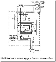
The resistance-type starter, Fig. 19, employs a heavy-duty resistance in series with the line conductors. The drop of voltage through this resistance produces a reduced voltage at the motor terminals. The starting current of the motor is reduced in direct proportion to the reduction of the voltage applied to the motor terminals.
It should be noted, however, that in the case of a resistance starter being used to reduce the voltage to half value, for example, the current drawn from the line will also be half of the full voltage value, whereas if an autotransformer starter is used, the current drawn from the line varies as the square of the voltage ratio of the transformer. Thus, if half voltage is applied to the motor terminal from the secondary of the autotransformer, the current drawn from the line will only be one-fourth the full-voltage value.
Step-Down Transformer Starting
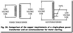
The voltage step-down transformer method of starting is rarely used because it is more expensive than the autotransformer method. A step-down voltage transformer consists of two complete coils or wind ings, while an autotransformer requires but one tapped coil or winding. The comparison is shown in Fig. 20.
