POWER FACTOR CONTROL AND ENERGY OPTIMISATION
Voltage control
In addition to their use for soft-start and speed control, thyristor voltage regulators are sometimes marketed as power factor controllers and/or energy optimisers for cage motors. Much of the hype surrounding their introduction has evaporated, but users should remain sceptical of some of the more extravagant claims, which can still be found.
The fact is that there are comparatively few situations where considerations of power factor and/or energy economy alone are suYcient to justify the expense of a voltage controller. Only when the motor operates for very long periods running light or at low load can suYcient savings be made to cover the outlay. There is certainly no point in providing energy economy when the motor spends most of its time working at or near full load.
Both power factor control and energy optimisation rely on the fact that the air-gap Xux is proportional to the supply voltage, so that by varying the voltage, the Xux can be set at the best level to cope with the prevailing load. We can see straightaway that nothing can be achieved at full load, since the motor needs full Xux (and hence full voltage) to operate as intended. Some modest savings in losses can be achieved at reduced load, as we will see.
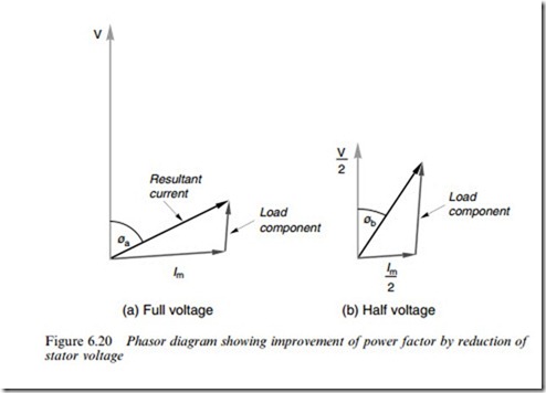
If we imagine the motor to be running with a low-load torque and full voltage, the Xux will be at its full value, and the magnetising component of the stator current will be larger than the work component, so the input power factor (cos fa) will be very low, as shown in Figure 6.20(a).
Now suppose that the voltage is reduced to say half (by phasing back the thyristors), thereby halving the air-gap Xux and reducing the mag- netising current by at least a factor of two. With only half the Xux, the rotor current must double to produce the same torque, so the work current reXected in the stator will also double. The input power factor (cos fb) will therefore improve considerably (see Figure 6.20(b)). Of course the slip with ‘half-Xux’ operation will be higher (by a factor of four), but with a low-resistance cage it will still be small, and the drop in speed will therefore be slight.
The success (or otherwise) of the energy economy obtained depends on the balance between the iron losses and the copper losses in the motor. Reducing the voltage reduces the Xux, and hence reduces the eddy current and hysteresis losses in the iron core. But as we have seen above, the rotor current has to increase to produce the same torque, so the rotor copper loss rises. The stator copper loss will reduce if (as in Figure 6.20) the magnitude of the stator current falls. In practice, with average general-purpose motors, a net saving in losses only occurs for
light loads, say at or below 25% of full load, though the power factor will always increase.
Slip energy recovery (wound rotor motors)
Instead of wasting rotor circuit power in an external resistance, it can be converted and returned to the mains supply. Frequency conversion is necessary because the rotor circuit operates at slip frequency, so it cannot be connected directly to the mains.
In a slip energy recovery system, the slip frequency a.c. from the rotor is Wrst rectiWed in a 3-phase diode bridge and smoothed before being returned to the mains supply via a 3-phase thyristor bridge converter operating in the inverting mode (see Chapter 4). A transformer is usually required to match the output from the controlled bridge to the mains voltage.
Since the cost of both converters depends on the slip power they have to handle, this system (which is known as the static Kramer drive) is most often used where only a modest range of speeds (say from 80% of synchronous and above) is required, such as in large pump and compressor drives. Speed control is obtained by varying the Wring angle of the controlled converter, the torque–speed curves for each Wring angle being fairly steep (i.e. approximating to constant speed), thereby making closed-loop speed control relatively simple.
