When no mechanical load is applied to the shaft, the IM works on no-load. In terms of energy conversion, the IM input power has to cover the core, winding, and mechanical losses. The IM has to develop some torque to cover the mechanical losses. So there are some currents in the rotor. However, they tend to be small and, consequently, they are usually neglected.
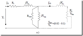
The equivalent circuit for this case is similar to the case of ideal no-load, but now the core loss resistance R1m may be paralleled by a fictitious resistance Rmec which includes the effect of mechanical losses.
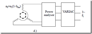
The measured values are P0, I0, and Vs. Voltages were tested varying from, in general, 1/3Vsn to 1.2Vsn through a Variac.
I0 Rs jXsl I’r0 jX’rl
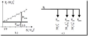
Figure 7.5 No-load motor operation
a.) equivalent circuit, b.) no-load loss segregation, c.) power balance, d.) test arrangement
As the core loss (eddy current loss, in fact) varies with (ω1Ψ1)2, that is approximately with Vs2, we may end up with a straight line if we represent the function
P0 −3R Is 02 = piron + pmec = f V( s2 ) (7.44)
The intersection of this line with the vertical axis represents the mechanical losses pmec which are independent of voltage. But for all voltages the rotor speed has to remain constant and very close to synchronous speed.
Subsequently the core losses piron are found. We may compare the core losses from the ideal no-load and the no-load motoring operation modes. Now that we have pmec and the rotor circuit is resistive (Rr′/S0n >>Xrl′), we may calculate approximately the actual rotor current Ir0.
SR ‘0rn Ir0’≈ Vsn (7.45)
pmec ≈ 3R ‘ISr 0nr0′2 (1−S0n )≈ 3R ‘ISr 0nr0′2 ≈ 3V Isn r0′ (7.46)
Now with Rr′ known, S0n may be determined. After a few such calculation cycles, convergence toward more precise values of Ir0′ and S0n is obtained.
Example 7.3. No-load motoring
An induction motor has been tested at no-load at two voltage levels: Vsn = 220V, P0 = 300W, I0 = 5A and, respectively, Vs′ = 65V, P0′ = 100W, I0′ = 4A. With Rs = 0.1Ω, let us calculate the core and mechanical losses at rated voltage piron, pmec. It is assumed that the core losses are proportional to voltage squared.
Solution
The power balance for the two cases (7.44) yields
P0 −3R Is 02 = (piron )n + pmec
|
P ‘ 3R I ‘0 − s 0 2 = (piron )n Vsns + pmec |
(7.47) |
V ‘ 2
|
iron n 220 mec From (7.47), |
|
|
piron = 2921−.50.−087395.25 = 216.17W pmec = 292.5− 216.17 = 76.328W |
(7.48) |
100 −3 0.1 4⋅ ⋅ = (p ) + p = 95.2
Now, as a bonus, from (7.46) we may calculate approximately the no-load current Ir0′.
Ir0’≈ 3pVmecsn = 763⋅.220328 = 0.1156A (7.49)
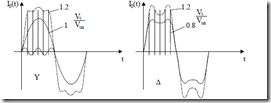
It should be noted the rotor current is much smaller than the no-load stator current I0 = 5A! During the no-load motoring tests, especially for rated voltage and above, due to teeth or/and back core saturation, there is a notable third flux and emf harmonic for the star connection. However, in this case, the third harmonic in current does not occur. The 5th, 7th saturation harmonics occur in the current for the star connection.
For the delta connection, the emf (and flux) third saturation harmonic does not occur. It occurs only in the phase currents (Figure 7.6).
As expected, the no-load current includes various harmonics (due to mmf and slot openings).
Figure 7.6 No-load currents, a.) star connection, b.) delta connection
They are, in general, smaller for larger q slot/pole/phase chorded coils and skewing of rotor slots. More details in Chapter 10. In general the current harmonics content decreases with increasing load.
THE MOTOR MODE OF OPERATION
The motor mode of operation occurs when the motor drives a mechanical load (a pump, compressor, drive-train, machine tool, electrical generator, etc.). For motoring, Te > 0 for 0 < n < f1/p1 and Te < 0 for 0 > n > –f1/p1. So the electromagnetic torque acts along the direction of motion. In general, the slip is 0 < S < 1 (see paragraph 7.2). This time the complete equivalent circuit is used (Figure 7.1).
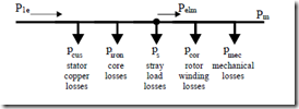
The power balance for motoring is shown in Figure 7.7.
Figure 7.7 Power balance for motoring operation
The motor efficiency η is η = input shaft electricpower power = PP1me = Pm + pCos + pironP+m pCor + ps + pmec (7.50) The rated power speed n is
n = f1 (1−S) (7.51)
P1
The rated slip is Sn = (0.08 – 0.006), larger for lower power motors.
The stray load losses ps refer to additional core and winding losses due to space (and eventual time) field and voltage time harmonics. They occur both in the stator and in the rotor. In general, due to difficulties in computation, the stray load losses are still assigned a constant value in some standards (0.5 or 1% of rated power). More on stray losses in Chapter 11.
The slip definition (7.15) is a bit confusing as Pelm is defined as active power crossing the airgap. As the stray load losses occur both in the stator and rotor, part of them should be counted in the stator. Consequently, a more realistic definition of slip S (from 7.15) is
S = P pcor−ps = P1e −pCosp−corpiron −ps (7.52)
elm
As slip frequency (rotor current fundamental frequency) f2n = Sf1n it means that in general for f1 = 60(50) Hz, f2n = 4.8(4) to 0.36(0.3) Hz.
For high speed (frequency) IMs, the value of f2 is much higher. For example, for f1n = 300 Hz (18,000 rpm, 2p1 = 2) f2n = 4 – 8 Hz, while for f1n = 1,200 Hz it may reach values in the interval of 16 – 32 Hz. So, for high frequency (speed) IMs, some skin effect is present even at rated speed (slip). Not so, in general, in 60(50) Hz low power motors.
GENERATING TO POWER GRID
As shown in paragraph 7.2, with S < 0 the electromagnetic power travels from rotor to stator (Peml < 0) and thus, after covering the stator losses, the rest of it is sent back to the power grid. As expected, the machine has to be driven at the shaft at a speed n > f1/p1 as the electromagnetic torque Te (and Pelm) is negative (Figure 7.8).
Figure 7.8 Induction generator at power grid
The driving motor could be a wind turbine, a Diesel motor, a hydraulic turbine etc. or an electric motor (in laboratory tests).
The power grid is considered stiff (constant voltage and frequency) but, sometimes, in remote areas, it may also be rather weak.
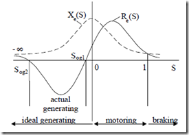
To calculate the performance, we may use again the complete equivalent circuit (Figure 7.1) with S < 0. It may be easily proved that the equivalent resistance Re and reactance Xe, as seen from the power grid, vary with slip as shown on Figure 7.9.
Figure 7.9 Equivalent IM resistance Re and reactance Xe versus slip S
It should be noted that the equivalent reactance remains positive at all slips. Consequently, the IM draws reactive power in any conditions. This is necessary for a short-circuited rotor. If the IM is doubly fed as shown in Chapter 19, the situation changes as reactive power may be infused in the machine through the rotor slip rings by proper rotor voltage phasing, at f2 = Sf1.
Between S0g1 and S0g2 (both negative), Figure 7.9, the equivalent resistance Re of IM is negative. This means it delivers active power to the power grid.
The power balance is, in a way, opposite to that for motoring (Figure 7.10).
P2electric
Pshaft
pCos piron ps pCor pmec
Figure 7.10. Power balance for generating
The efficiency ηg is now
η = electricshaft power power inputoutput = PP21electricshaft = P2electric + pCos +Pp2ironelectric+ pCor + ps + pmec (7.53)
Above the speed nmax = Pf11 (1−S0g2 ); S0g2 < 0 , (7.54)
as evident in Figure 7.9, the IM remains in the generator mode but all the electric power produced is dissipated as loss in the machine itself.
Induction generators are used more and more for industrial generation to produce part of the plant energy at convenient timing and costs. However, as it still draws reactive power, “sources” of reactive power (synchronous generators, or synchronous capacitors or capacitors) are also required to regulate the voltage in the power grid.
Example 7.4 Generator at power grid
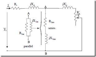
A squirrel cage IM with the parameters Rs = Rr′ = 0.6 Ω, Xsl = Xrl′ = 2 Ω, X1ms = 60 Ω, and R1ms = 3 Ω (the equivalent series resistance to cover the core losses, instead of a parallel one)–Figure 7.11 – works as a generator at the power grid.
Let us find the two slip values S0g1 and S0g2 between which it delivers power to the grid.
Solution
The switch from parallel to series connection in the magnetization branch, used here for convenience, is widely used.
The condition to find the values of S0g1 and S0g2 for which, in fact, (Figure 7.9) the delivered power is zero is
Re(S0g )= 0.0 (7.55)
Figure 7.11 Equivalent circuit with series magnetization branch Equation (7.55) translates into
|
In numbers: |
1ms s S0g S0g 1ms 1ms 1ms s + R1msX’rl2 +R1ms2Rs + R Xs( 1ms + X’rl )2 = 0 |
(7.56) |
|
2 3.6 0.6⋅ 2S10g + 0.6 3( 2 + 602 + 2 3 0.6⋅ ⋅ )S10g + |
(7.57) |
(R + R ) R ‘r 2 + R ‘r (R 2 + X 2 + 2R R )+
+ 3 2⋅ 2 + 32 ⋅0.6 + 0.6(60 + 2)2 = 0
