Motor Repair
Before a motor fault can be determined, a test must be made to find out exactly what the problem is. The first step is to make sure the motor turns over easily by hand. You might be able to stop right here, as the trouble might be in the motor bearings, causing undue friction that will in turn cause the motor to heat up and, finally, burn out. Continue by checking for an open circuit, using a continuity tester; attach one of the test leads to the motor lead and the other test lead to another motor lead. If the indicator functions, the circuit is closed. Then touch one lead with one of the test leads and the other lead to the end of the motor shaft. If nothing occurs (no light, no needle swing, etc), the motor is not grounded. Should this test indicate a ground (the lamp of the tester lights, the needle swings, etc.), disassemble the motor and try to locate the fault.
Once the motor has been disassembled, always retest the leads at this time, as grounded leads are often the problem. If the winding is burned out, the burnt appearance may be seen easily when the motor is disassembled. The odor of burnt insulation is another sign that is easily detected. If the grounded part of the winding or leads cannot be found by this method and tests show that a ground does exist, the only alternative is to rewind the motor.
COLLECTING DATA
Assuming the armature is to be rewound, the next step is to collect suffi cient data while dismantling the old winding. These data will enable the new winding to be installed correctly.
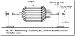
Begin by mounting the armature in suitable armature horses such as those shown in Fig. 19-1. Then, as the old winding is dismantled, mark the slots and commutator segments from which the first coil and leads are removed. This can be done with a conventional scratch awl or metal file. One small punch mark can be placed under the slot that held the top coil side and two dots under the slot that holds the bottom side of the same coil. The top leads are then traced out to the commutator, and each bar that they connect to should be marked with one dot. Next trace the bottom leads to the commutator, and each of the bars they connect to should be marked with two dots. This marking should be done to both lap and wave windings and is a positive way of keeping the core and the com mutator marked so they may be reconnected properly. Keep in mind that the bottom lead will be the lead with which the coil is started and the top lead will be the ending lead once the coil is wound.
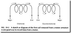
If deemed necessary, a sketch or diagram may be made of the first few coils removed to indicate which way the coils are wound. The sketch can be made similar to the ones in Fig. 19-2.
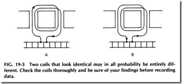
In removing the old winding, remember that the coils will be com pacted and not stretched out as shown in the diagrams in Fig. 19-2. This requires careful examination to determine just exactly how the coils are wound. For example, look at the two coils in Fig. 19-3. At first glance, they both look almost identical. However, a closer examination will reveal that coil A is wound right-handed while coil B is wound left handed. When recording data for an armature, make certain that they are recorded exactly as found.
In addition to marking the core and commutator and keeping a dia gram of the winding and connections, the following data should be care fully collected as the old winding is removed:
• Turns per element
• Size of conductor
• Insulation on conductor
• Coil insulation
• Slot insulation (layers, type, and thickness)
• Extension of slot insulation from each end of core
• Overall extension of the winding from the core, both front and back
If the preceding items are carefully observed and recorded, little dif ficulty should be encountered in replacing most windings correctly. It does, however, require practice to obtain coils of exactly the proper size and shape so that they will fit neatly and compactly in the armature. No book can do this for the winder. He or she must practice winding to ob tain this ability.
Wire bands are sometimes used on large armatures having heavy coils to hold the coil ends securely in place. If the core has open slots, bands are often used over the core to hold the wedges in place. High grade steel piano wire is commonly used for this purpose and can be ob tained in various sizes from motor repair suppliers.
When a banding machine is not available, a lathe can be used to hold the armature while the bands are wound on. A layer of paper or cloth is usually placed under the band. Cloth makes the best foundation for bands placed on the coils ends, as the cloth tends to keep the bands from slipping off. A layer of fish paper can be used under bands placed around the core. Grooves about Ya 2 in. deep are usually provided for the bands on cores with open slots.
The paper should be cut carefully to the exact width of this groove, so it will fit snugly and without sticking out at either side. The banding wires should be wound on under tension, so they will be firm and tight when completed. A simple tension clamp or brake can be made by cutting two strips of fiber 114 by 1Y2 by 6 in. and bolting them together with two small bolts, using wing nuts on each end. Place these pieces of fiber in the tool post of the lathe and run the wire between them at very slow speed. Then, by adjusting the two wing nuts, any desired tension may be ob tained.
To start the first band, make a hook of heavier wire and attach the band wire securely to this hook. Then slip the hook under the ends of a couple of coils close to the ends of the slots and start winding the band wire on the core. Make two or three gradual turns around the core to get the band wire over to the first slot. As the first turn is wound in the slot, narrow strips of tin should be placed in the slot under it and every few inches apart around the core. Drawing the first turn tight will hold these strips in place, and other turns are then wound on over them. Wire should be wound with the turns tightly together until this groove is full. Then fold up the ends of several of the tin strips to hold these wires in place, run the wire across to the next groove with a couple of gradual turns around the core, and start the next band without cutting the wire. Con tinue in this manner until all the bands are on. Then, before releasing the tension on the wire, run a thin layer of solder across each group of band wires in several places to keep them from loosening when the end wires are cut.
After cutting the wires between the bands, cut these ends off to the proper length, so that they will come directly under one of the tin clamp ing strips. Then fold in the ends of all these strips tightly and solder them down with a thin layer of solder.
These tin strips are usually about 15 mils thick and 114 in. wide and should be cut just long enough so that their ends will fold back over the bands about 114 in.
While stripping armatures, note that one coil is on top of the others in the usual arrangement. Unwinding the top coils would reveal another coil which is now on top of the remaining coils and so on until the last coil is reached. Such coil progressions are known as either right or left.
For example, assume that the first coil is placed in a slot, that the next coil is placed in the slot to the right of the first one, that the next coil is placed to the right of that one, and so on. This progression is wound to the right and is known by the same name. In winding a motor to the right, it is necessary to turn the armature toward the left after each coil is wound into the slots. In all cases, the armature should be positioned so th t the commutator faces the winder-in either stripping or winding and all measurements and figures are taken with the armature in this position.
If it is desired to have the coils progressing to the left, it becomes necessary to turn the armature to the right after each coil is placed in the slots. The first coil is placed in its slots with each successive coil being wound into the slots toward the left.
The direction in which coils progress has no influence on the direc tion of rotation. The choice is a matter of preference depending on which way is easier for the winder.
LEAD CONNECTIONS
In collecting data from the old windings, make sure that the lead connec tions are accurately recorded. This can be accomplished by using some or all of the following suggestions:
Find the top side of the coil. If the armature is wound with one coil upon another, take the side of the coil which has the ending lead. If the armature is of the form type, more care must be taken in determining the lead connections as one side of each coil is in the top of the slot and one side is in the bottom. In the latter type, the top leads are usually separated from the bottom ones by tape. Ascertain the number of coils per slot and remove that number of leads from the segments. The coils per slot may be calculated by the following equation:
2. Mark the segment which contains the leads that have been removed. Make a loop in each of the leads and leave that coil momentarily. Cut the back leads of enough coils so that they may be pulled out until the coil with the looped leads is whole. Be sure not to disturb the bottom leads on removing the coils. Unwind the coil until the other leads of the coil come to the commutator and record where they connect to the bars.
3. Remove the top leads as directed and make loops in them. Desolder and pull out all top leads. Use a test lamp to touch each of the looped leads with one test lead and the commutator with the other lead. When the light lights, that is the commutator bar to which the bottom lead connects. Check carefully to make certain that the test lamp does not light on another bar also. If so, clean out mica between bars and test again.
4. Mark the bars where each of the top and bottom leads for the number of coils per slot connect. Remove enough coils to remove the coil with the looped leads as a whole coil. If these loops are on the ending side or top of the coil, then these leads with the loops are sure to be the top leads.
5. In some rare cases, the bottom leads may be found on top of the winding. Therefore, the coil should be unwound to be certain where the beginning and end of the leads are located. Remember that beginning leads are bottom leads and that ending leads are top leads; record them as such.
Determining lead connections for conventional windings is a much easier task. Merely follow the lead to the commutator and mark the top lead; the number will depend on the number of coils per slot. Next unwind the coil until the bottom leads are found. Mark the commutator where they are located with a light punch or scratch awl, making certain they will not be erased easily. Use one mark for the top leads and two marks for the bottom leads as discussed previously.
Some winders prefer to use a test lamp to determine the various leads, but this method is not always reliable. Some armature windings can be so badly burned that a test lamp will not give accurate readings. Therefore, it is always best to unwind a coil to collect the data.
RECORDING DATA
Once the leads have been located, take the slot having the top leads and with a piece of metal-lay it in the center of the slot so it will extend the length of the slot and to the commutator. A straightedge such as a metal rule is ideal for this step. Just be sure to position it in the center of the slot. The bar on which the straightedge strikes the commutator is known as bar 1 and the next bar as 2. If the top lead falls several bars either to the right or left of the bar straight out from the slot, the top lead connec tion will be so many to the right or left, counting this bar as 1, the next as 2, and so on.
When there is more than one coil per slot, follow the same procedure, except list the data with the top lead nearest bar 1first.
After finding the top lead connection, locate the bottom lead. In a lap-wound armature, where the bottom leads connect out next to the top leads, record “bottom leads next to top leads” on the left or right depend ing on which side of the tops they are, or record “bottom leads adjacent to top leads” on the right or left.
The following suggestions may help in recording these data:
1. Locate the bars in which the bottom leads connect, and begin ning with bar 1(and counting it as 1), count over as was done for the top leads- only, however, to where the bottom leads connect.
2. With a wave winding, the top leads and bottom leads are con nected to commutator bars at quite a number of bars away from each other. Collecting data for this type of connection varies some what from that for a lap winding, and there are two methods nor mally used to record these data:
a. After having found the top lead connections, count from the bar having the top lead and designate this bar as bar 1un til encountering the bar that has the bottom lead for that coil. This is known as the commutator span, between top and bot tom leads, and the bars containing these leads are counted when arriving at this commutator span.
b. Take the bottom side of the coil or the side where the bot tom leads of the coil enter and place a straightedge in the cen ter of the slot out to the commutator, as done previously. As soon as bar 1is located, count over toward the direction of the bottom leads. The bottom leads may be 5 and 6 left. The data would then read “tops 1 and 2 right, bottoms 5 and 6 left, wave wound.”
Diagrams such as Fig. 19-4 help to show more clearly the various connections and how they are made. Diagrams also eliminate the need for a lot of written instructions, saving the winder much time.
DATA CARDS
Recording data from a motor nameplate and/or by tests and examina tions has been successfully accomplished in several different ways. Some repairmen merely write out the data on a card and possibly accompany these data with a wiring diagram or two. A sample of these data follows:
General Electric Y2 hp. Type RSA, frame 415, form D, 120/240 V, 10/5 A, 1750 rpm, one phase, 60 cycles, serial number 76894. Armature, 21 slots, 41 bars, 43 coils, with 1 dead coil. Wound right-handed, coils progress right. Top lead 4, 5 right, bottoms 5, 6 left, commutator span 1-21. 12 turns #18 SOE, coil span 1-7. Retrogressive connections.
In shops doing much motor repair work, however, a standard form is better. In general, such a form is a systematic method of listing informa tion concerning motors that are repaired. When properly organized and thoroughly understood, these forms are not only time-saving devices but can help prevent an oversight in collecting data, since there is a section for all necessary information. The information on the card will be the same as described in the preceding example.


