Overload Set Up
When setting up an overload relay to protect a motor in a given situation, the following two questions must be considered:
1. Should the overload relay be set to the Hand Reset or Auto Reset position?
2. What load current value should the overload relay be set at?
Hand Reset Position
In the case of motors that are manually controlled, the overload relay must be set to Hand reset. The motor will stop if the overload relay trips out and will not restart automatically, regardless of the position of any control switch, until the overload relay is reset.
Auto Reset Position
In the case of motors that are automatically controlled, the overload relay may be set to Hand or Auto reset as the situation requires.
· If the automatic starting up of the driven machine may cause danger, then the overload relay must be on Hand reset. This means that an operator is alerted that the overload relay has tripped out and has to be manually reset. Part of the operator’s function is to ensure that the restarting of the machine does not cause any health or safety problem.
· If the automatic starting up of the driven machine will not cause danger, then the overload relay may be on Auto reset. This means that the operation of the machine is interrupted for the least amount of time possible. This is very important in various cases for example: air compressors, refrigeration units, liquid pumps where the liquid may congeal ( set ) if allowed cool in the pipe work, etc. An operator could still be aware of the fact that the overload relay tripped out. This information could be recorded automatically if necessary.
Load Current Setting
Overload relays are designed to operate between 110% and 120% of the set value. It is essential that they be accurately set to the Full Load Current of the motor.
· If set too high, they will not provide proper protection for the motor. Damage may be done to the motor windings through overheating if overloading occurs.
· If set too low they will operate before the motor is fully loaded. This will result in low output from the driven machine and the motor will not be operating at full efficiency.
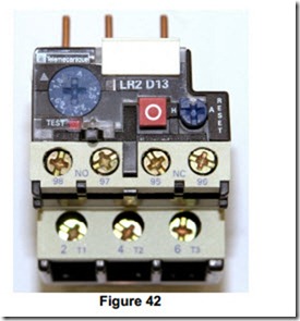
The setting up of overload relays, differ slightly as type and / or manufacturer changes. The overload relay shown in Figure 39 has a sealable transparent cover over all its adjustable items. Lifting this cover provides access to all these items.
One of these is a large blue dial which is adjustable using a screwdriver. This dial is marked in terms of motor Full Load Current. It is simply rotated so that the required figure in Amps is in line with the white arrow on the body of the relay. The overload relay in Figure 42 is suitable for any motor with a FLC of 1.6 Amps to 2.5 Amps. The next relay in this range is suitable for any motor with a FLC of 2.5 Amps to 4 Amps. In this way all motor FLC values are catered for.
Just below the blue dial there is a small red button. Pressing this button with a small flat screwdriver will simulate the tripping function. The N/C auxiliary contact 95-96, opens and N/O auxiliary contact, 97-98 closes. A small orange coloured flag appears to the right of the blue dial. This is very useful for checking the control circuit wiring during commissioning.
The red button with a white circle in the centre is simply a local stop button. Pressing it opens the N/C auxiliary contact, 95-96. It does not close the N/O auxiliary contact, 97-98.
The blue reset button may be set in either the Hand or Auto position as necessary. This may be done using a suitably sized screwdriver. When set in the Hand position the button is allowed to pop out under spring pressure. It must now be pressed to reset after a trip has taken place. When set in the Auto position ( press in using screwdriver before attempting to turn ) the button is held in. This means that the unit will reset itself after a trip has taken place.
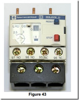
The overload relay shown in Figure 43 has a sealable hinged cover over all its adjustable items. Pulling this cover from the right hand side provides access to all these items.
One of these is a small white dial which is adjustable using a screwdriver. This dial is marked in terms of motor Full Load Current. It is simply rotated so that the pointer is in line with the required figure in Amps, on the body of the relay. This overload relay is suitable for any motor with a FLC of 2.5 Amps to 4 Amps. The next relay in this range is suitable for any motor with a FLC of 4 Amps to 6 Amps. In this way all motor FLC values are catered for.
Above and to the right of the white dial there is a small black Test lever. Pressing this lever with a small flat screwdriver, in the direction of the arrow above it, will simulate the tripping function. The N/C auxiliary contact 95-96, opens and N/O auxiliary contact, 97-98 closes. The letter T will appear on the lever. This is very useful for checking the control circuit wiring during commissioning.
The red button is simply a local stop button. Pressing it opens the N/C auxiliary contact, 95-96. It does not close the N/O auxiliary contact, 97-98.
To the right of the white dial there is a small white tab with H printed on it. This indicates that the relay is supplied set in the Hand reset position.
To change to Auto reset this white tab must be prised away with a small flat screwdriver. This reveals a small blue lever. When this lever is moved downwards, an A appears indicating that the relay is now set in the Auto reset position. The Test lever will not operate in the Auto position.

