NOZZLE-FLAPPER ASSEMBLY
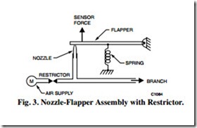
The nozzle-flapper assembly (Fig. 3) is the basic mechanism for controlling air pressure to the branch line. Air supplied to the nozzle escapes between the nozzle opening and the flapper. At a given air supply pressure, the amount of air escaping is determined by how tightly the flapper is held against the nozzle by a sensing element, such as a bimetal. Thus, controlling the tension on the spring also controls the amount of air escaping. Very little air can escape when the flapper is held tightly against the nozzle.
To create a branchline pressure, a restrictor (Fig. 3) is required. The restrictor and nozzle are sized so that the nozzle can exhaust more air than can be supplied through the restrictor when the flapper is off the nozzle. In that situation, the branchline pressure is near zero. As the spring tension increases to hold the flapper tighter against the nozzle, reducing the air escaping, the branchline pressure increases proportionally. When the spring tension prevents all airflow from the nozzle, the branchline pressure becomes the same as the mainline pressure (assuming no air is flowing in the branch line). This type of control is called a “bleed” control because air “bleeds” continuously from the nozzle.
With this basic mechanism, all that is necessary to create a controller is to add a sensing element to move the flapper as the measured variable (e.g., temperature, humidity, pressure) changes. Sensing elements are discussed later.
