Direct On Line Starter
A DOL starter connects the three main lines ( L1, L2 and L3 ) directly to the motor terminals when the start button is pressed. The drawing of a DOL starter is generally done in two separate stages. These are called the Power Circuit and the Control Circuit.
Power Circuit
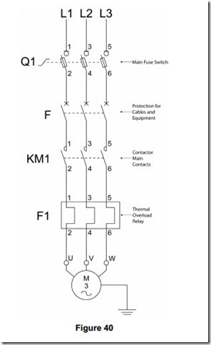
The power circuit shows all the components or parts of components required to handle the load current of the motor. Remember that the motor in question may be a small 1.5 kW ( 2 HP ) or a large 225 kW ( 300 HP ). As the motor power rating increases so too must the current rating of the contactor, overload relay and supply cables.
N.B. When wiring circuits, the supply should be fed in on the low number terminal and out on the high number terminal. See figure 40.
Control Circuit
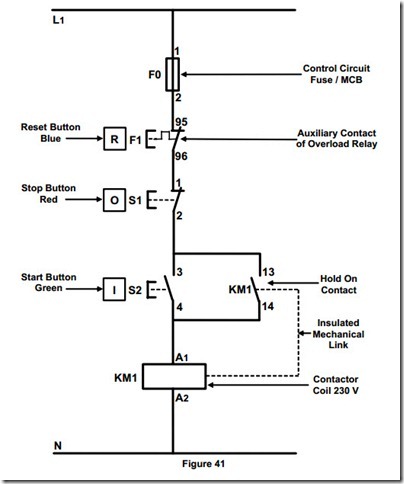
The control circuit shows all the components or parts of components required to control the motor. These components are basically the same regardless of the power rating of the motor in question.
Note When wiring circuits, the supply should be fed in on the low number terminal and out on the high number terminal. See figure 41.
Circuit Description
Refer to the circuit illustrated in Figure 41.
The motor being controlled by KM1 will START if:
· Supply voltage is present between L1 and N
· The control fuse F0 is good
· The normally closed ( NC ) contact 95 – 96 is closed
· The stop pushbutton S1 is not operated
· The start pushbutton S2 is operated
· The coil is energised by the presence of a voltage and the circuit is complete through the coil to the neutral
· The auxiliary contact 13 – 14 ( NO ) is closed by the operation of the coil
· When the start pushbutton S2 is released current continues to flow through the auxiliary contact 13 – 14 ( hold on contact ), the coil remains energised and the motor continues to run.
The motor being controlled by KM1 will STOP if:
· The control circuit fuse blows or MCB trips or is switched off.
· The overload trips or F1 is pressed causing 95 – 96 ( NC ) contact to open
· The stop button S1 is pressed
· The voltage reduces to a level which cannot keep the coil energised
· The supply fails


