OIL SCREEN CLOGGING
Oil screen clogging is more likely in winter when ice formation and sludge are prevalent. Water freezes in small particl es which collect on the oil screen. Sludge is the result of a conglomer-
ation of water, carbon and partly burned fuel particles. Water is the chief offender as cold weather sludge emulsion does not form when water is absent. Higher engine temperatures, effi cient crankcase ventilation and less short-run driv ing are among the means possible to minimize the detrimental effects of water in the oil.
Water seldom is troublesome in summer be cause it collects less rapidly and th e higher operat ing temperatures more effectively remove any that does accumulate. Oil screen clogging still is pos sible in summer, however, but the most likely causes are varnish due to oil break-down at high temperatures.
Whenever the oil pan is removed for any reason, the screen should be cleaned. The by-pass, if fitted, should be checked to insure it is in proper working condition. If the screen is collapsed or if there is an opening through which oil can pass without going through the screen, a replacement is necessary.
REMOVING OIL PUMPS
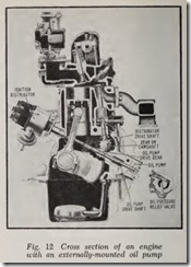
In most cars the gear on the camshaft drives both the oil pump and ignition distributor. And when the drive gear for these units is attached to the oil pump shaft and is coupled directly to the distributor drive shaft, Fig. 12, it is essential that the pistons are positioned properly with relation to ignition timing before the oil pump is removed or installed.
Note that the oil pump in this case, Fig. 12, is attached to the outside of the engine and, there fore, it can be removed without dropping the oil pan. Before removing the pump, however, first turn over the engine to bring Nq. 1 piston on its compression stroke and continue cranking until it reaches its firing position. Lift off the distributor cap and make a chalk mark on the distributor housing adjacent to the rotor, which should be in the firing position for No. 1cylinder. Then remove the capscrews which attach the pump to the en gine and lift it off. Unless it cannot be avoided, do not disturb the position of the distributor while the pump is off the engine.
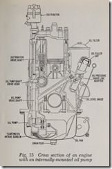
Fig. 13 shows an engine in which the same arrangement is employed. This means that the same precautions regarding ignition timing must be taken. But since the oil pump is located inside the engine, the oil pan must be removed. After removing the pan, unfasten the pump from its mounting and take it out.
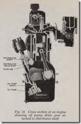
The design shown in Fig. 14 is similar to the above except that the drive gear is attached to the distributor drive shaft. No special precautions relative to ignition timing are necessary in this case since the pump can be taken down without disturbing the timing.
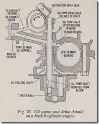
Another example is shown in Fig. 15. A separate gear is used to drive the distributor and oil pump shafts, both meshing with the gear on the cam shaft. In removing the pump from these engines, no attention need be paid to ignition timing. Note, however, that the oil pump drive gear is splined to the drive shaft. And after removing the oil pan and taking out the pump from below, the drive gear is removed separately.
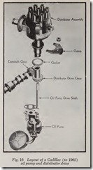
Fig. 16 shows the oil pump and distributor drive on Cadillac engines to 1962. The top of the distributor drive gear is slotted to receive the tangs at the lower end of the distributor drive shaft. The oil pump drive shaft has a flatted side which fits into a similarly-shaped hole in the dis tributor drive gear. With this construction the usual precautions for ignition timing outlined for Fig. 12 must be observed.
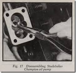
On Studebaker Champion engines, the same _ arrangement as that shown in Fig. 12 is used to drive the oil pump and distributor and the same precautions relative to ignition timing apply in this case. However, removing the pump is a piece by-piece proposition and is accomplished as follows: Take off the pump cover and pick out the “C” washer from the pump shaft, Fig. 17. Then remove the pump body and pull out the shaft and gears.
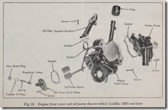
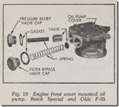
On some cars, a gear type oil pump is housed in the engine front cover, Figs. 18 and 19. When servicing these pumps, because they are mounted above the level of the oil in the crankcase, special precautions must be taken before starting the engine.
On the Cadillac type, before installing the oil filter, fill the oil passages in the filter support bracket with engine oil. This will allow the pump to prime itself when the engine is started.
On the Buick Special and Olds F-85 type, the pump gear pocket should be packed with vaseline (not chassis lube). Reinstall the gears so the vaseline is forced into every cavity of the gear pocket and between the gear teeth. Unless the pump is packed as directed, it may not prime itself when the engine is started.
GEAR OIL PUMPS
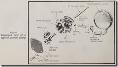
The most commonly used oil pumps are those of the positive gear type, Fig. 20, which are driven directly from the gear on the camshaft. It consists of two gears enclosed in a close-fitting housing. As the gears turn, oil is taken from the inlet pipe and is directed to the spaces between the teeth and is carried around to the outlet where the action of the teeth meshing together squeezes it out of the spaces and forces it from the pump. In many pumps of this type, the oil pressure relief valve is built into the pump body. To inspect the pump, remove the cover and wash all parts in kerosene or other suitable solvent. Examine the gears for dam age, excessive backlash between the teeth, and looseness of the drive gear on the shaft.
If a .010″ feeler gauge can be inserted between any mating teeth, consider the backlash excessive and replace the gears. Move the shaft from side to side in the housing and if more than just a per ceptible movement is felt, replace the pump hous ing or if the housing is provided with bushings, replace the bushings.
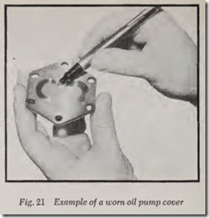
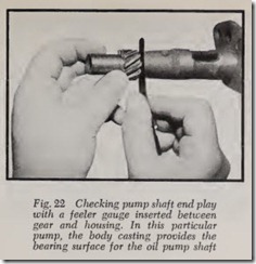
Fig. 21 shows a pump cover that has been worn out by too much end play in the pump shaft which permitted the pump gear to ride against the cover. This cover must be replaced because one of the controlling factors of oil pump pressure is the clearance between the bottom of the gears and the pump cover. Always check the shaft for end play either by moving the gear up and down or by inserting a feeler gauge between the gear and pump body, Fig. 22. If there is space enough to insert a .005″ feeler the drive gear should be replaced . Some pumps have replaceable drive gears; in others the gear is integral with the shaft.
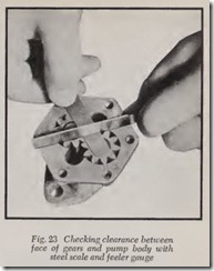
Check the clearance between the face of the gears and pump body, using a machinist’s scale and feeler gauge, Fig. 23. If the clearance exceeds .005″ the gears should be replaced.
After disassembling the pump as explained be low, check the bearing surface of the shaft for any evidence of roughness and replace the shaft if it is not smooth.
Examine the condition of the idler gear pin. In most cases the pin is integral with the pump body and, when worn, requires a new pump body.
Some idler gears have a replaceable bushing. If the gear is satisfactory from the standpoint of gear lash but loose on the idler pin, install a new bushing.
To disassemble the pump, remove the cover and pick out the idler gear. If the oil pressure relief valve is built into the pump, unscrew the spring retainer and take out the parts, being sure to note their arrangement so they may be rein stalled without difficulty.
The next step is to remove the upper drive gear if one is used. Usually it is pressed on the shaft and kept from rotating by a straight pin driven in the hole drilled through the gear and shaft. File off one end of the pin and, using a small drift or punch, drive out the pin and take off the gear. In a few pumps of this type, the gear is held by a Woodruff (semicircular) key. And before remov ing the gear, note carefully whether the gear is positioned flush with the end of the shaft or how far it extends beyond the end so that the new gear may be installed accordingly.
After removing the upper drive gear, withdraw the shaft and lower gear. Then inspect all parts in the manner previously described, replacing those that are worn or otherwise damaged.
When assembling the pump, dip the gears in engine oil to provide for initial lubrication and priming. There must be a perfect gasket seal between the pump body and cover in order to assure suction. A few pumps do not use a gasket between these parts but where gaskets are used, the thickness is very important-the gasket deter mining the clearance between the face of the pump gears and cover which in turn affects oil pressure.
ROTOR OIL PUMPS
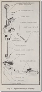
A typical rotor pump, Fig. 24 is driven by the gear on the camshaft in the same manner as conventional gear pumps. It differs, however, in that it has an inner and outer rotor in the pump body instead of gears. In operation, oil is drawn from the crankcase through the oil screen and passes through a drilled passage to the pump from which it is forced through drilled passages to the engine bearings.
To disassemble and inspect the pump, remove the cover and gasket. Hold a hand over the cover opening and, with the pump upside down, turn the drive shaft until the outer rotor slips out. Slide the shaft and inner rotor assembly out of the pump body. Wash all parts in kerosene and dry with compressed air, if available.
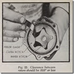
Match the rotors together, Fig. 25, and measure the clearance as illustrated. It should be .010″ or less; if more replace both rotors.
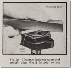
Place a straight edge across the pump body between the screw holes, Fig. 26, and, with a feeler gauge, measure the clearance between the top of the rotors and the straight edge. This measurement should be .004″ or less. Press the outer rotor to one side and measure the clearance, Fig. 27, between the rotor and body. This mea surement should be .008″ or less. Should either of the above measurements ·be more than specified, replace the pump body.
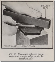
Place the straight edge across the cover, Fig. 28, and try to insert a .001″ feeler gauge between the cover and straight edge. If the feeler can be inserted or if the cover is scratched or grooved, replace it with a new cover.
When installing a new rotor on the shaft, press it on until the end of the shaft is flush with the face of the rotor. Drill the pin hole and install the pin. Slide the rotor and shaft into the pump body.
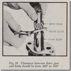
Press the drive gear on the shaft until end play on the shaft is .003″ to .010″. Press the rotor down into the body and measure the clearance as shown in Fig. 29. Install the pin and peen over both ends. If the pin holes do not line up, drill a new hole between the gear and shaft, making the hole at right angles to the other hole. Slide the outer rotor into the pump body. Install a new gasket and tighten the cover screws down evenly.
INSTALLING OIL PUMPS
Replacing an oil pump is a matter of reversing the work done when it was removed. However, if the pump is of the type having the drive gear fastened to the oil pump shaft, Fig. 11, with the ignition distributor shaft coupled directly to it, first tum over the engine to bring No. 1 piston to its firing position. Then tum the distributor shaft so the rotor is in the position to fire No. 1 cylinder and note the angle at which the tongue or slot on the lower end of the distributor shaft faces when installed in the engine.
Having carefully noted this angle, install the oil pump and mesh the drive gear with the gear on the camshaft so the tongue or slot in the pump shaft will engage the end of the distributor shaft. Fasten the pump temporarily and install the dis tributor. If the distributor rotor is in the No. 1 firing position, the installation is correct and the pump may be fastened permanently. However, if the rotor must be moved in order to engage the pump shaft to the distributor shaft, remove the pump and mesh the gears correctly.
OIL PRESSURE RELIEF VALVES
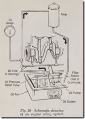
Since the output of any positive displacement type pump, such as those described, is many times the normal requirement of the engine oiling sys tem, an oil pressure relief valve is used to by-pass the excess oil back into the oil pan when the pressure exceeds th e rated capacity of the pump. This is shown schematically in Fig. 30.
Whenever an oil pump is removed for cleaning or repairs, the oil relief valve should be taken apart and cleaned. This must not be overlooked because if the valve is held open with sludge or carbon it will not seat properly and will therefore allow oil to leak through it before the pressure reaches the proper maximum. This will decrease the amount of oil supposed to be delivered to the
bearings.
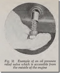
Wher e the r elief valve is not b uilt as part of the oil pu mp, it is connected in th e oil line but is usu ally accessible from the outside of the engine for inspection, Fig. 31. This construction is used on L-head Chrysler-bu ilt en gines and a few others.
