Objectives
• To learn basics of troubleshooting
• To learn troubleshooting techniques
• To understand various measuring devices and their functions
• To learn different testing methods.
Introduction
In the last two chapters we have studied about symbols, measuring meters, reading control circuits, etc. This would help in building a planned and strategic approach for troubleshooting.
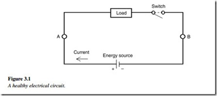
In a healthy state, any basic circuit that has a load and energy source has circuit paths, as shown in Figure 3.1.
Current flows in a closed circuit between two electrically unequal potential points. Points A and B are any two points across which voltage is measured. The conductor offers resistance to this flow of electrons (i.e., current) depending upon the material.
Generally electrical problems can be classified under two broad types.
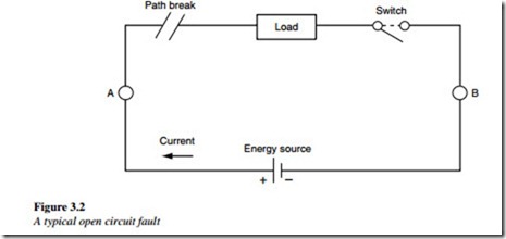
1. A connection does not exist where it should. This is an open circuit fault and can be detected using a continuity tester (Figure 3.2 illustrates this type of fault).
2. A connection exists where none should. This is called a short-circuit fault and can lead to excessive current accompanied by mechanical forces and heating of circuit conductors. Such fault happen due to insulation failures and can be detected using insulation testing instruments.
The process of detecting these faults and rectifying the circuit to restore normal operating condition is called troubleshooting. We will discuss about the open circuit fault first.
Current has a tendency to flow between two points that are at an unequal potential (electrically), provided the path between the two points is electrically conductive.
• Resistance offered by the path is known as ‘Resistance’ ohm)
• Electrical potential is denoted as ‘volts’
• Flow of electrons between two points is termed as ‘Current’ (amp). Therefore, while troubleshooting, the following points have to be checked:
0 Continuity of path (i.e., resistance)
0 Electric potential at two points of the path (i.e., voltage)
0 Flow of electrons through the path (i.e., current).
An electrical circuit is made up of different paths and works on different voltages. Let us, therefore, identify the path that should be complete, also, when and how it is completed. Moreover, if it does not complete, let us identify the reason.

