Meters
The more common electric meters may be roughly divided into the following classes:
According to the function performed, as:
I . Ammeters,
2. Voltmeters,
3. Wattmeters.
According to the circuit on which they are used, as:
1. Alternating current,
2. Direct current.
According to the principle of operation, as:
I. Permanent-magnet, moving-coil,
2. Dynamometer,
3. Magnetic- vane,
4. Induction.
The essential parts of these instruments generally include:
1 . Means for providing a deflection torque (obtained by interaction of magnetic fields),
2. A spring or other means to provide a countertorque,
3. A pointer to indicate the resultant position of the moving element of the meter.
PERMANENT-MAGNET, MOVING-COIL METERS
A permanent-magnet, moving-coil type of meter is suitable for measuring only de, and its operation depends on the reaction between the current in a movable coil and the field of a fixed permanent magnet. The essential parts of an instrument of this type are shown in Fig. 1.
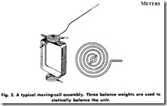
The permanent magnet supplies a uniform magnetic field through pole pieces and across the air gap in which a moving coil wound with fine wire is located. The moving coil (Fig. 2) is provided with hardened steel pivots fitted into highly polished jewels that allow the moving coil to rotate with as little friction as possible. Springs of carefully selected phosphor-bronze strip are used to lead current into and away from the moving system, and also to supply a restraining torque. The position of the moving coil is indicated by a pointer which moves over a suitably marked scale. The entire moving-coil assembly is made very light in weight to decrease the load on the sharp steel pivots as much as possible. In operation, the current through the moving coil provides a field which interacts with the field of the permanent magnet, and thus supplies a deflecting torque.
Damping is accomplished by winding the moving coil on a light aluminum frame. Eddy currents are set up in the frame because of the motion of the coil in the permanent-magnet field. The field produced by the eddy currents interacts with the permanent-magnet field in such a manner as to oppose the motion of the coil, thus causing it to come to rest quickly.
Ammeters
In general practice, it is not feasible to send more than 0.1 ampere directly through the moving coil; hence, to accommodate larger cur rents, shunts are provided, such as those shown in Fig. 3. A shunt for instrument service is usually made from a material having a very low temperature coefficient of resistance and a low thermal emf to copper.
The low temperature coefficient of resistance is necessary to assure that the resistance of the shunt, and therefore the instrument indication, will not change when the shunt carries currents which are sufficiently high to cause it to become quite warm. The second requirement-low thermal emf to copper-is important, because if the shunt terminals become unequally heated, an appreciable voltage may be superimposed on the normal voltage drop of the shunt and thus cause an error.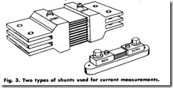
Millivoltmeters
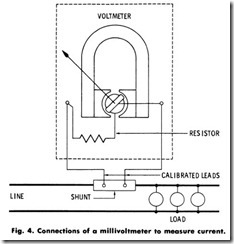
De millivoltmeters for use with shunts (Fig. 4) generally require 10 to 15 milliamperes at 30 to 200 millivolts for full-scale deflection, de pending on the class of instrument. One common type of portable instrument requires 25 millamperes at 200 millivolts for full-scale deflection. The corresponding switchboard instruments, which need not be held to such close limits of accuracy, require approximately 20 milliamperes at 50 millivolts for full-scale deflection.
Note that the instruments just described are suitable for use only on direct current because the field supplied by the instrument magnet is unidirectional. Impressing 60-hertz current on such an element will result in a torque pulsation which tends to move the instrument pointer upscale, followed 1I 120 of a second later by a torque pulsation which tends to drive the pointer an equal distance in the opposite direction.
Hence, the pointer merely vibrates a small distance on each side of the zero point on the meter scale.
Voltmeters
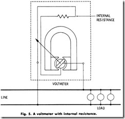
To make the meter movement suitable for reading de voltage, a resistance is inserted in the instrument circuit, as shown in Fig. 5. This simply limits the current to such a value that full deflection of the instrument pointer is obtained when the maximum voltage which it is desired to read is applied to the instrument. For example, if an ammeter is rated at 10 milliamperes (0.01 ampere) for full-scale deflection, and it is required to make it a voltmeter having a full-scale rating of 150 volts,
it would require a total resistance of 150/0.01 = 15,000 ohms.
The milliammeter moving coil has some resistance-about 20 ohms-so only 14,980 ohms of additional resistance need be added. This resistor is made of very stable material which is not affected by ordinary changes in temperature. The amount of constant resistance
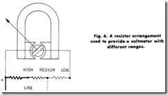
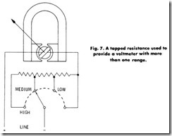
added is sufficient to compensate for the effect of the moving system resistance which changes with temperature. Hence, the same current will always flow through the element when a given voltage is applied, regardless of the temperature at which the instrument operates. Several different ranges can be obtained by using separate tapped resistors (known as multipliers), as shown in Fig. 6, or by tapping off various points on the same resistor, as shown in Fig. 7.
It is possible to make voltmeters that require a very small amount of current for their operation. A common type of portable instrument, rated at 150 volts, requires about 10 milliamperes for full-scale deflec tion. It is customary to refer to de voltmeters as possessing a certain number of ohms-per-volt. For example, the 150-volt instrument just mentioned requires 10 milliamperes for full-scale deflection. Hence, its resistance must be 15,000 ohms. Since the resistance is 15,000 ohms and the full-scale volts are 150, the instrument has 15,000/150, or a rating of 100 ohms-per-volt. Other portable voltmeters can be made which are considerably more sensitive. Some types on the market have a resistance as high as 20,000 ohms-per-volt.

