IMs are, in general, designed for 60(50) Hz; when used for variable speed with variable V/f supply, they operate at variable frequency. Below the rated frequency, the machine is capable of full flux linkage, while above that, flux weakening occurs.
For given load speed and load torque with variable V/f supply, we may use IMs with 2p1 = 2, 4, 6. Each of them, however, works at a different (distinct) frequency.
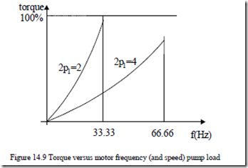
Figures 14.9 show the case of quadratic torque (pump) load with the speed range of 0 to 2000 rpm, load of 150 kW at 2000 rpm, 400 V, 50 Hz (network). Two different motors are used: one of 2 poles and one of 4 poles.
At 2000 rpm the 2 pole IM works at 33.33 Hz with full flux, while the 4 pole IM operates at 66.66 Hz in the flux-weakening zone. Which of the two motors is used is decided by the motor costs. Note however, that the absolute torque (in Nm) of the motor has to be the same in both cases.
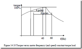
For a constant torque (extruder) load with the speed range of 300 – 1100 rpm, 50kW at 1200 rpm, network: 400 V, 50 Hz, two motors compete. One, of 4 pole, will work at 40 Hz and one, of 6 pole, operating at 60 Hz (Figure 14.10). Again, both motors can satisfy the specifications for the entire speed range as the load torque is below the available motor torque. Again the torque in Nm is the same for both motors and the choice between the two motors is decided by motor costs and total losses.
While starting torque and current are severe design constraints for IMs designed for constant V/f supply, they are not for variable V/f supply.
effect is important for constant V/f supply as it reduces the starting current and increases the starting torque. In contrast to this, for variable V/f suply, skin effect is to be reduced, especially for high performance speed control systems.
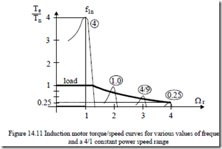
Breakdown torque may become a much more important design factor for variable V/f supply, when a large speed zone for constant power is required. A spindle drive or an electric car drive may require more than 4-to-1 constant power range (Figure 14.11).
The peak torque of IM is approximately
2 2 2
Tek ≈ 3 ![]() 2Vπphnf1n ff11n 2pL1sc = Tekf1n ff11n (14.4)
2Vπphnf1n ff11n 2pL1sc = Tekf1n ff11n (14.4)
The peak torque for constant (rated) voltage is inversely proportional to frequency squared. To produce a 4/1 constant power speed range, the peak torque has to be 4 times the rated torque. Only in this case, the motor may produce at f1max = 4f1n, 25% of rated torque.
Consequently, if the load maximum torque is equal to the rated torque, then at 4f1n the rated power is still produced.
In reality, a breakdown torque of 400% is hardly practical. However, efforts to reduce the short-circuit leakage inductance (Lsc) have led up to 300% breakdown torque.
So there are two solutions to provide the required load torque/speed envelope: increase the motor rating (size) and costs or increase the flux (voltage) level in the machine by switching from star to delta connection (or by reducing the number of turns per phase by switching off part of the stator coils). The above rationale was intended to suggest some basic factors that guide the IM design.
Relating the specifications to a dedicated machine geometry is the object of design (or dimensioning). This enterprise might be as well be called sizing the IM.
Because there are many geometrical parameters and their relationships to specifications (performance) are in general nonlinear, the design process is so complicated that it is still a combination of art and science, based solidly on existing experience (motors) with tested (proven) performance. In the process of designing an induction motor, we will define a few design factors, features, and sizing principles.
DESIGN FACTORS
Factors that influence notably the induction machine design are as follows:
Costs
Costs in most cases, are the overriding consideration in IM design. But how do we define costs? It maybe the costs of active materials with or without the fabrication costs. Fabrication costs depend on machine size, materials available or not in stock, manufacturing technologies, and man power costs.
The costs of capitalized losses per entire motor active life surpass quite a few times the initial motor costs. So loss reduction (through higher efficiency or via variable V/f supply) pays off generously. This explains the rapid extension of variable speed drives with IMs worldwide.
Finally, maintenance costs are also important but not predominant. We may now define the global costs of an IM as
Global costs material = costs + fabrication and selling costs +
+losses capitalized costs + maintenance costs (14.5.)
Global costs are also a fundamental issue when we have to choose between repairing an old motor or replacing it with a new motor (with higher efficiency and corresponding initial costs).
Material limitations
The main materials used in IM fabrication are magnetic-steel laminations, copper and aluminum for windings, and insulation materials for windings in slots.
Their costs are commensurate with performance. Progress in magnetic and insulation materials has been continuous. Such new improved materials drastically affect the IM design (geometry), performance (efficiency), and costs.
Flux density, B(T), losses (W/kg) in magnetic materials, current density J (A/mm2) in conductors and dielectric rigidity E (V/m) and thermal conductivity of insulation materials are key factors in IM design.
Standard specifications
IM materials (lamination thickness, conductor diameter), performance indexes (efficiency, power factor, starting torque, starting current, breakdown torque), temperature by insulation class, frame sizes, shaft height, cooling types, service classes, protection classes, etc. are specified in national (or international) standards (NEMA, IEEE, IEC, EU, etc.) to facilitate globalization in using induction motors for various applications. They limit, to some extent, the designer’s options, but provide solutions that are widely accepted and economically sound.
Special factors
In special applications, special specifications–such as minimum weight and maximum reliability in aircraft applications–become the main concern. Transportation applications require ease of maintaining, high reliability, and good efficiency. Circulating water home pumps require low noise, highly reliable, induction motors.
Large compressors have large inertia rotors and thus motor heating during frequent starts is severe. Consequently, maximum starting torque/current becomes the objective function.
DESIGN FEATURES
The major issues in designing an IM may be divided into 5 area: electrical, dielectric, magnetic, thermal and mechanical.
Electrical design
To supply the IM, the supply voltage, frequency, and number of phases are specified. From this data and the minimum power factor and a target efficiency, the phase connection (start or delta), winding type, number of poles, slot numbers and winding factors are calculated. Current densities (or current sheets) are imposed.
Magnetic design
Based on output coefficients, power, speed, number of poles, type of cooling, and the rotor diameter is calculated. Then, based on a specific current loading (in A/m) and airgap flux density, the stack length is determined.
Fixing the flux densities in various parts of the magnetic circuit with given current densities and slot mmfs, the slot sizing, core height, and external stator diameter Dout are all calculated. Choosing Dout, which is standardized, the stack length is modified until the initial current density in the slot is secured.
It is evident that sizing the stator and rotor core may be done many ways based on various criteria.
Insulation design
Insulation material and its thickness, be it slot/core insulation, conductor insulation, end connection insulation, or terminal leads insulation depends on machine voltage insulation class and the environment in which the motor operates.
There are low voltage 400V/50Hz, 230V/60Hz, 460V/60Hz 690V/60Hz or less or high voltage machines (2.3kV/60Hz, 4kV/50Hz, 6kV/50Hz). When PWM converter fed IMs are used, care must be exercised in reducing the voltage stress on the first 20% of phase coils or to enforce their insulation or to use random wound coils.
Thermal design
Extracting the heat caused by losses from the IM is imperative to keep the windings, core, and frame temperatures within safe limits. Depending on application or power level, various types of cooling are used. Air cooling is predominant but stator water cooling in the stator of high speed IMs (above 10,000 rpm) is frequently used. Calculating the loss and temperature distribution and the cooling system represents the thermal design.
Mechanical design
Mechanical design refers to critical rotating speed, noise, and vibration modes, mechanical stress in the shaft, and its deformation displacement, bearings design, inertia calculation, and forces on the winding end coils during most severe current transients.
We mentioned here the output coefficient as an experience, proven theoretical approach to a tentative internal stator (stator bore) diameter calculation. The standard output coefficient is Dis2⋅L, where Dis is the stator bore diameter and L, the stack length.
Besides elaborating on Dis2⋅L, we introduce here the rotor tangential stress σtan (in N/cm2), that is, the tangential force at rotor surface at rated and peak torque.
This specific force criterion may be used also for linear motors. It turns out that σtan varies from 0.2 to 0.3 N/cm2 for hundred watt IMs to less than 3 to 4 N/cm2 for large IMs. Not so for the output coefficient Dis2⋅L, which is related to rotor volume and thus increases steadily with torque (and power).


