DIAGNOSTIC TESTING FOR MOTORS
The following factors affect the insulation systems in motors:
● High temperature
● Environment
● Mechanical effects such as thermal expansion and contraction, vibration, electromag- netic bar forces, and motor start-up forces in the end turns
● Voltage stresses during operating and transient conditions
All these factors contribute to loss of insulation integrity and reliability.
These aging factors interact frequently to reinforce one another’s effects. For example, high-temperature operation could deteriorate the insulation of a stator winding, loosen the winding bracing system, and increase vibration and erosion. At some point, high-temperature operation could lead to delamination of the core and internal discharge. This accelerates the rate of electrical aging and could lead to a winding failure. Nondestructive diagnostic tests are used to determine the condition of the insulation and the rate of electrical aging. The description of the recommended diagnostic tests for the insulation system of motors and the conditions they are designed to detect are discussed below.
Stator Insulation Tests
An electrical test is best suited to determine the condition of electrical insulation. The tests on insulation systems in electrical equipment can be divided into two categories:
1. High-potential (hipot), or voltage-withstand tests
2. Tests that measure some specific insulation property, such as resistance or dissipation factor
Tests in the first category are performed at some elevated ac or dc voltage to confirm that the equipment is not in imminent danger of failure if operated at its rated voltage. Various standards give the test voltages that are appropriate to various types and classes of equipment. They confirm that the insulation has not deteriorated below a predetermined level and that the equipment will most likely survive in service for a few more years. However, they do not give a clear indication about the condition of the insulation.
The second category of electrical tests indicates the moisture content; presence of dirt; development of flaws (voids), cracks, and delamination; and other damage to the insulation.
A third category of tests includes the use of electrical or ultrasonic probes that can deter- mine the specific location of damage in a stator winding. These tests require access to the air gap and energization of the winding from an external source. These tests are considered an aid to visual inspection.
DC Tests for Stator and Rotor Windings
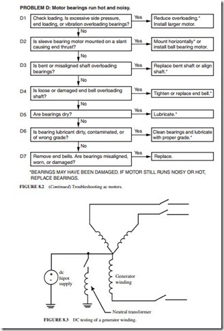
These tests are sensitive indicators to the presence of dirt, moisture, and cracks. They must be performed off-line with the winding isolated from ground, as shown in Fig. 8.3.
Suitable safety precautions should be taken when performing all high-potential tests. When high-voltage dc tests are performed on water-cooled windings, the tubes or mani- folds should be dried thoroughly, to remove current leakage paths to ground and to avoid the possibility of damage by arcing between moist patches inside the insulating water tubes. For greater sensitivity, these tests can be performed on parts of the windings (phases) isolated from one another.
The charge will be retained in the insulation system for up to several hours after application of high dc voltages. Hence, the windings should be kept grounded for several hours after a high-voltage dc test to protect personnel from a shock.
Tests using dc voltages have been preferred over the ones using ac voltages for routine evaluation of large machines for two reasons:
1. The high dc voltage applied to the insulation during a test is far less damaging than high ac voltages due to the absence of partial discharges.
2. The size and weight of the dc test equipment are far less than those of the ac test equip- ment needed to supply the reactive power of a large winding.
Insulation Resistance and Polarization Index
The polarization index (PI) and insulation resistance tests indicate the presence of cracks, contamination, and moisture in the insulation. They are commonly performed on any motor and generator winding. They are suitable for stator and insulated rotor windings.
The insulation resistance is the ratio of the dc voltage applied between the winding and ground to the resultant current. When the dc voltage is applied, the following current com- ponents flow:
1. The charging current into the capacitance of the windings.
2. A polarization or absorption current due to the various molecular mechanisms in the insulation.
3. A “leakage” current between the conductors and ground (the creepage path). This compo- nent is highly dependent on the dryness of the windings.
The first two components of the current decay with time. The third component is mainly determined by the presence of moisture or a ground fault. However, it is relatively constant. Moisture is usually absorbed in the insulation and/or condensed on the end winding surfaces. If the leakage current is larger than the first two current components, then the total charging current (or insulation resistance) will not vary significantly with time. Therefore, the dryness and cleanliness of the insulation can be determined by measuring the insulation resistance after 1 min, and after 10 min. The polarization index is the ratio of the 10-min to the 1-min reading.
Test Setup and Performance
Several suppliers, such as Biddle Instruments and Genrad, offer insulation resistance meters that can determine the insulation resistance accurately by providing test voltages of 500 to 5000 V dc. For motors and generators rated 4 kV and higher, 1000 V is usually used for testing the windings of a rotor, and 5000 V is used for testing the stator windings.
To perform the test on a stator winding, the phase leads and the neutral lead (if accessible) must be isolated. The water must be drained from any water-cooled winding, and any hoses removed or dried thoroughly by establishing a vacuum (it is preferable to remove the hoses because vacuum drying is usually impossible).
The test instrument is connected between the neutral lead or one of the phase leads and the machine frame (Fig. 8.3). To test a rotor winding, the instrument should be connected between a lead from a rotor winding and the rotor steel. During the test, the test leads should be clean and dry.
Interpretation
If there is a fault or the insulation is punctured, the resistance of the insulation will approach zero. The Institute of Electrical and Electronics Engineers (IEEE) standard recommends a resistance in excess of VL-L 1 MD. If the winding is 13.8 kV, the minimum acceptable
insulation resistance is 15 MD. This value must be considered the absolute minimum since modern machine insulation is on the order of 100 to 1000 MD. If the air around the machine had high humidity, the insulation resistance would be on the order of 10 MD.
The insulation resistance depends highly on the temperature and humidity of the winding.
To monitor the changes of insulation resistance over time, it is essential to perform the test under the same humidity and temperature conditions. The insulation resistance can be corrected for changes in winding temperature. If the corrected values of the insulation resistance are decreasing over time, then there is deterioration in the insulation.
However, it is more likely that the changes in insulation resistance are caused by changes in humidity. If the windings were moist and dirty, the leakage component of the current (which is relatively constant) will predominate over the time-varying components. Hence, the total current will reach a steady value rapidly.
Therefore, the polarization index is a direct measure of the dryness and cleanliness of the insulation. The PI is high (>2) for a clean and dry winding. However, it approaches unity for a wet and dirty winding.
The insulation resistance test is a very popular diagnostic test due to its simplicity and low cost. It should be done to confirm that the winding is not wet and dirty enough to cause a failure that could have been averted by a cleaning and drying procedure. The resistance testing has a pass/fail criterion. It cannot be relied upon to predict the insulation condition, except when there is a fault in the insulation.
The high-potential tests, whether dc or ac, are destructive testing. They are not generally recommended as maintenance-type tests.
For stator windings rated 5 kV or higher, a partial discharge (PD) test, which in the past has been referred to as corona, should be done. The level of partial discharge should be determined because it can erode the insulation and lead to insulation aging.
DC High-Potential Testing
The dc high-potential (hipot) test is a nondestructive test used to evaluate the dielectric strength of the groundwall insulation. The voltage applied across the windings is given by
where Vo is the operating voltage and Vdc-hipot is the voltage applied across the windings during the dc hipot test. The casing of the motor is maintained at ground voltage. The leakage current between the windings and the core is measured. The insulation resistance is obtained by dividing the voltage imposed across the windings by the leakage current. The test indicates that the groundwall insulation is able to withstand high voltage without being damaged.
Note that this test is different from the destructive ac and dc high-potential tests performed by the manufacturer of the motor. These tests are performed to determine the maximum voltage that the insulation of the motor can withstand. The voltage reached during these tests is much higher than the voltage recommended for the nondestructive dc high-potential test. They are performed by a qualified operator to prevent the destruction of the motor.
Surge Testing
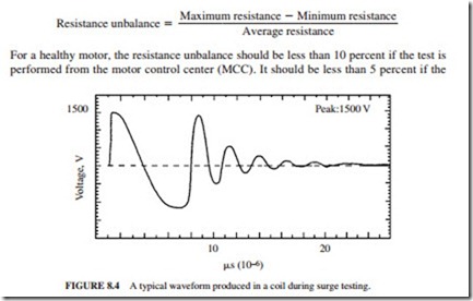
The dc high-potential test confirms the integrity of the insulation. However, it does not indicate a failure of the insulation between the turns of the windings (interturn fault). The surge test is used to detect the early stages of insulation failures in the windings such as coil-to-coil failures, short circuits, ground, and misconnections. During the surge test, brief voltage surges (pulses) are applied across the coil. These pulses produce a momentary volt- age stress between the turns of the coil. Figure 8.4 illustrates a typical response of a coil.
Each coil has a unique signature waveform, which can be displayed on the screen of the equipment during the test. The waveform obtained during the surge test is directly related to the inductance of the coil.
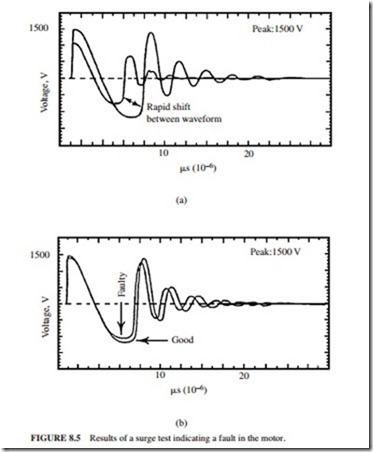
A surge test can detect an interturn fault due to weak insulation. If the voltage spike is greater than the dielectric strength of the interturn insulation, one or more turns could be shorted out of the circuit. The number of turns in the coil will drop, leading to a reduction in the inductance of the coil and an increase in the frequency of the waveform produced by the surge test. If the coil has an interturn fault or a phase-to-phase fault, the waveform produced during the test could become unstable. It could shift rapidly to the left and right and back to its original position (Fig. 8.5a).
A comparison is done between the surge tests performed on each of the phases. A healthy three-phase motor should have three identical phases. Therefore, the results of the surge tests performed on each of the phases should be identical. Any differences found between the three results indicate that there is a fault in the motor (Fig. 8.5a and b).
Terminal-to-Terminal Resistances (Winding Resistances)
This test involves measuring the resistance of each of the three phases. The resistance unbalance is given by
test is performed at the motor. The larger resistance unbalance (10 percent instead of 5 per- cent) is allowed when the test is performed from the MCC due to the long cables between the MCC and the motor.
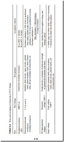
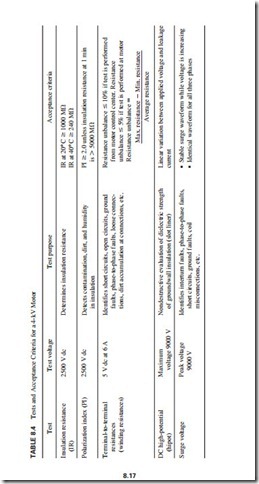
The voltage and current used during the test for 4-kV and 575-V motors are 5 V dc and 6 A, respectively. This test is used to detect short circuits, ground faults, phase-to-phase faults, loose connections, open circuits, dirt accumulation at connections, etc. Tables 8.3 and 8.4 list the tests required and acceptance criteria used for a 575-V and a 4-kV motor, respectively.
Tests for the Detection of Open Circuits in Induction Motor Rotor Cage Windings Severe thermal aging and failure of rotor core lamination insulation will occur as a result of open circuits in induction motor cage windings. Failure analysis of more than 6000 induc- tion motors confirmed that 10 percent of these failures occurred in the rotors. One-half of the rotor failures occurred in the cage winding. If a rotor winding cracks, the performance of the motor will degrade and the stator end windings could also get damaged.
Large and medium-size high-speed motors are the most susceptible to cracks in the cage winding. Large, low-speed motors driving high-inertia loads such as induced-draft (ID) and forced-draft (FD) boiler fans are also susceptible to this mode of failure. The bar extensions, short-circuit rings, and joints between these components are most susceptible to cracking. Cyclic mechanical stresses occurring during start-up lead to cracking by fatigue failure. These stresses are mainly produced by centrifugal forces and differential thermal expansion.
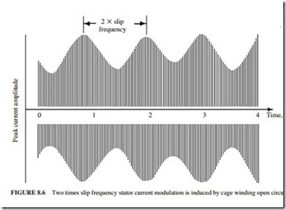
The impedance around the rotor periphery becomes unbalanced by an open circuit in a squirrel-cage rotor winding. The amplitude of the stator current waveform will fluctuate as the magnetic field rotates relative to the rotor surface due to the open circuit. Figure 8.6 illustrates this modulating effect.
Fluctuations in shaft speed can also be caused by broken bars or short-circuit rings. In a healthy rotor, the torque varies sinusoidally at twice the slip frequency. When a bar is aligned with the center of the stator pole, it develops the maximum torque. Some sections of the cage winding will not develop any torque if the rotor has an open circuit. The shaft will slow down slightly twice during each slip cycle. The presence of an open circuit can be verified by measurement of these speed fluctuations.
The two methods described below are used to detect open circuits in rotors. The stator current fluctuation test is performed on an operating and loaded motor. The normal power supply and driven equipment should be uncoupled before performing the manual rotation test.
Stator Current Fluctuation Test
This simple online technique has been used for many years. The current in one of the phases is monitored for fluctuations at twice the slip frequency. An ammeter is observed, or a cur- rent transformer output is monitored on a strip chart recorder or oscilloscope. The results should be interpreted by an experienced operator.
Manual Rotation Test
The motor is disconnected from its normal three-phase power supply for its off-line test. The driven equipment should be uncoupled unless it can be manually rotated with the motor. A single-phase ac supply is connected across two motor terminals. It has voltage rating of 10 to 25 percent of rated line-to-line volts and a kVA rating of 5 to 25 percent of rated kVA. The rotor is manually turned for one-half revolution while monitoring the variations in the current. A broken rotor cage winding is indicated by current fluctuations in excess of 10 percent. The current fluctuations can also be monitored on a strip chart recorder connected to the output of a current transformer.
It is important to note that the test time should not exceed 1 min due to rapid heating in the stator and rotor windings. The main limitation of this test is that it can only be conducted off-line. Therefore, breaks in cage windings may not be detected if they close up, giving low-resistance connections when centrifugal forces are removed.
