Magnetism
Most of the electrical units in a car employ not only electricity but also magnetism (produced by electricity) to make them work. The list of electro magnetic units includes the starting motor (and any other electric motors), generator, ignition coil, horn, horn relay, solenoids, cutout relay, current regulator, voltage regulator, electric windshield wiper and so forth.
A permanent magnet, which requires no elec tricity to keep it magnetized, is used in all speed ometers, in many ammeters and in the dash unit of the gasoline gauge. The best known permanent magnet is the horseshoe type often used as a toy.
One of the main purposes of this chapter is to explain briefly the relationship between magne tism and electricity so that the reader will under stand how the various electro-magnetic units work. A few of the statements concerning magne tism will have to be taken at their face value because a complete explanation would be likely to confuse the average reader and thus do more harm than good.
For some reason, whenever an electron is in motion, a magnetic field surrounds that electron. (The word “field” means the field of magnetic influence which surrounds the electron.) Like wise, whenever an electric current flows through a conductor, a magnetic field surrounds that con ductor. This total field is the sum of the fields surrounding all the electrons flowing through the wire. Therefore, the intensity of the field is pro portional to the amperage. For example, doubling the amperage douqles the strength of the mag netic field because twice the number of electrons are flowing.
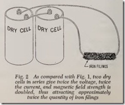
It is well known that a “magnetic” field attracts iron and steel. In Fig. 1 we show a wire which has been dipped in fine powder-like iron filings.. In Fig. 2 we have doubled the amperage (by doubling the voltage by using two dry cells in series) and it will be seen that the quantity of iron filings clinging to the wire has approximately doubled.
Before continuing our explanation of electro magnetism it is desirable to discuss permanent magnets.
Everybody knows that a magnet attracts iron, steel and cast iron. Obviously there is a magnetic field of attraction extending from the magnet to the metal it attracts.
When a piece of hard steel is magnetized it retains its magnetism almost indefinitely and therefore is called a pem1anent magnet. On the other hand, soft steel and cast iron lose almost all their magnetism as soon as the magnetizing influ ence is withdrawn. The magnetizing influence may be another magnet or a conductor through which a current flows.
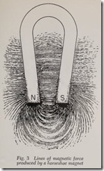
The size and shape of the field may be shown by placing the magnet under a sheet of cellophane and then sprinkling iron filings on the sheet, Fig.3. The filings arrange themselves in definite lines which are called lines of magnetic force, or lines of force for short. These lines exert a force when they attract a piece of iron. Note that the lines are concentrated at the ends or poles of the horseshoe.
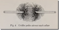
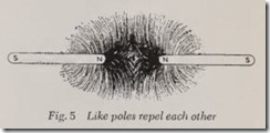
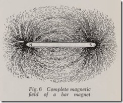
Experiment shows that the fields at the two poles are different. One is distinguished from the other by calling one the north pole and the other the south pole. Like poles repel each other and unlike poles attract each other. This statement can readily be proved by bringing the ends of two bar magnets close to each other as shown in Figs. 4 and 5. (A complete bar magnet is shown in Fig.6.) In Fig. 4 the unlike poles attract each other, the lines of force acting like the pull of so many rubber bands. In Fig. 5 the like poles are repelled, the lines of force acting as though they were stiff rubber bristles. In an electric motor it is magnetic repulsion which rotates the armature and thus changes electrical power into rotating mechanical power. On the other hand, in an electric gen erator, it is magnetic attraction by which mechanical power is changed into electrical power. These statements will be amplified later in this chapter.
A piece of iron or steel may be magnetized by placing it within the field of a permanent magnet. Fig. 4 will serve to illustrate the process. Assume that only the left bar is a permanent magnet and that the right bar is unmagneti zed when it is placed in the position shown. The magnetic field around the north pole of the permanent magnet at the left somehow transforms the piece at the right into a magnet, creating a south pole. Thus the magnet at the left attracts the formerly unmag netized piece at the right. It should be noted that whenever a piece of iron is magnetized at one end, an opposite pole appears at the right end. Fig. 6 illustrates the idea.
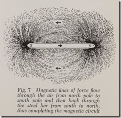
Magnetic lines of force “flow” through a circuit the same as does electricity. They flow from north to south pole, and then from south pole through the iron or steel magnet back to north pole, Fig. 7. There is a law for the flow of magnetism which corresponds to Ohm’s Law. Ohm’s Law states that: Volts (pressure or electromotive force) equals amperes (intensity or quantity of current) times resistance (to flow).
The corresponding magnetic law states that: Magnetomotive force (pressure) equals flux (in tensity of flow) times reluctance (resistance to flow). Reluctance of air is 2500 times that of iron, which means that for maximum flux, any air gaps in the circuit of iron or steel should be a minimum as to thickness or clearance.
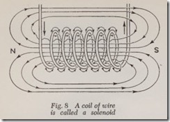
The force of an·electro-magnet is concentrated and intensified by making the wire into the form of a coil, Fig. 8, called a solenoid. The strength of the field is proportional to the number of amperes flowing through the coil times the number of turns in the coil.
The lines of force in the magnetic field are still further concentrated by the insertion of an iron core, Fig. 9. Solenoids with iron cores are used to open and close relay switches. Generator and motor armatures and field poles, and ignition coils are solenoids with iron cores. All solenoid cores are made of soft iron or soft steel so they will lose practically all their magnetism as soon as the solenoid circuit is broken. It is the solenoid coil which supplies the magneto-motive force just mentioned to create the magnetic circuit.
A magnetic field represents stored magnetic energy just the same as a compressed spring represents stored mechanical energy. The mechanical energy in a compressed spring is re leased when the spring is allowed to expand to its normal position.
The strength of the magnetic field in a solenoid increases or decreases as the current rises or falls. When current flow is constant the strength of the magnetic field is constant.
The magnetic field represents electric energy which is stored in magnetic form. When the sole noid circuit is first closed, the current rises to a maximum. During this time some of the energy in the current is converted into magnetic energy and stored as such in the field surrounding the sole noid. When the solenoid circuit is broken, the magnetic energy is transformed back into electric energy in the solenoid and a spark may jump across the switch points while they are being opened. The statements in this paragraph are of special interest in connection with ignition coils, as will be explained in the Ignition Chapter.
HOW GENERATOR WORKS
Fig. 10 is a diagram which shows the poles of two bar magnets, with arrows running from north to south pole. The arrows represent lines of force. (This diagram is nothing but a simplified drawing based on Fig. 4.)
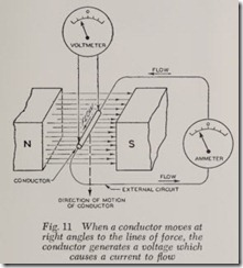
If a conductor is moved at right angles to the lines of force, Fig. 11, a voltage will be generated in the wire, causing a current to How through the wire and through the external circuit.
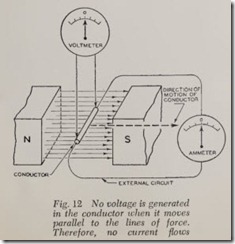
No voltage is produced in the conductor when it moves parallel to the lines of force, Fig. 12, because no lines of force are cut.
With north and south magnetic poles at left and right as shown in Fig. 11 and with the conductor moving downward, current How is in the direction shown by the arrows. If the wire is moved up ward instead of downward, current How is in the opposite direction, Fig. 13.
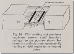
Fig. 14 shows a single armature coil placed in a magnetic field. Assume that the coil was made by connecting the ends of the conductors shown in Figs. 11 and 13. As the coil is rotated, current How is as shown by the arrows. This illustration ex plains the principle of the generator. Current Haws toward you in the left conductor and away from you in the right conductor.
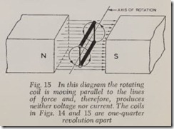
If the coil in Fig. 14 is rotated through one quarter revolution, the conductors are then mov ing parallel to the lines of force. No voltage is generated and therefore no current Haws, Fig. 15.
One-quarter revolution after Fig. 15 the coil is again in the same situation shown in Fig. 14.
To summarize: When a conductor is rotating in a field, Fig. 14, it cuts a maximum number of lines of force when moving at right angles to them, and cuts no lines when moving parallel to them, Fig. 1/2. During the rotation of a conductor from the parallel to right angle position (from Fig. 15 to 14) the number of lines of force cut is gradually
increased from nothin g t o the m aximum. Likewise when the conductor rotates from the right angle position to parallel, the number of lines cut is decreased from a maximum to nothing.
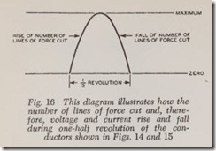
Fig. 16 shows how the lines cut, rise from zero to maximum and then fall to zero again during each half-revolution. Voltage and curr ent rise and fall in the same manner. This rise and fall occurs endlessly during all the half revolutions through which the conductors are rotated.
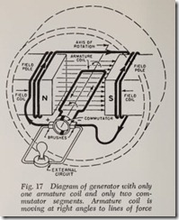
The principles discussed in connection with Figs. 1 to 16 will now be applied to a simple direct current generator with only one armature coil, Fig. 17. In this diagram there are the same mag netic poles and the same armature conductors as shown in the preceding pictures but some neces sary details have been added. Voltage, and the resulting current, are produced by the rot ation of the armature coil in the magnetic field.
The construction of the simple generator shown in Fig. 17 is as follows: The single armature coil is located in slots in a cylindrical piece of soft steel called the armature core ( not shown). The ends
of the coil are soldered to semicircular segments of copper to form the “commutator.” The two segments are insulated from each other. Two copper composition “brushes” are pressed against the commutator, thus providing a sliding electrical contact when commutator and armature coil are rotated. The brushes, of course, are stationary. That is, they do not rotate. The brushes are sup ported in suitable holders which, for simplicity, are not shown. For the same reason the brush springs which hold the brushes against the com mutator are not shown.
The magnetic field is produced electrically by coils of wire which are wound around the iron “field poles” (these are solenoids with iron cores but they are never called that. The terms used are field coils and field poles). The two coils are in series and are connected to the brushes. The external circuit is also connected to the brushes.
Even though the pole pieces and the armature core are made of soft iron or soft steel, a slight amount of magnetism (residual magnetism) re mains in them from the last time the generator was used. If the generator is a new one it must be initially magnetized by connecting it to a battery for a moment. Therefore, a generator has a slight but not negligible magnetic field when it is not in use.
When the armature coil is first rotated, a slight voltage is produced, causing a slight current to flow through the field coils. This current increases the strength of the magnetism in the field coils and in this way, in a few seconds, the voltage in the generator is built up to its normal value and the generator is ready for use.
Note that the field coil circuit and the external circuit are in parallel. Therefore, the current pro duced by the armature coil divides at the brushes. In an actual generator, about 1/15 of the current produced in the armature goes to the fields and the balance to the external circuit.
When the field circuit is in parallel with the external circuit, the device is called a “shunt” generator because some of the current produced is shunted into the field circuit.
When the generator is running, the magnetic lines of force produced by the armature and the magnetic lines of force produced by the field coils attract each other and try to prevent armature rotation. Therefore, engine power is required to pull apart or cut these lines of force in order to drive the generator. This attraction is the same in principle as the attraction of the two bar magnets shown in Fig. 4.
Current flows out into the external circuit through the positive ( + ) brush and returns by way of the negative (-) brush to the armature coil. One half revolution later, the right and left hand sides of the armature coil have changed places but so have the two segments; therefore,
current still continues to flow as shown-and so on for an infinite number of half revolutions. In other words, this is called a direct current gen erator because current and voltage always flow in the same direction.
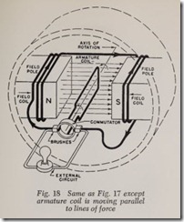
Fig. 18 represents any quarter revolution before or after Fig. 17. At this time the armature coil is moving parallel to the lines of force and, there fore, no voltage or current are generated.
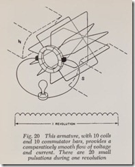
When the armature coil is moving from Fig. 18 to Fig. 17, there is a rise in voltage and current from zero to a maximum, and then when the coil moves from Fig. 17 to Fig. 18, there is a drop in current and voltage from a maximum to zero. (Within limits, the faster the armature runs the greater is the voltage and current generated.) Fig. 19 sho s how voltage and current rise and fall during three complete revolutions of the armature coiInstead of the pulsating current produced by a single armature coil, a smooth current is desirable and this is obtained by increasing the number of coils on the armature. An actual generator has upwards of 20 coils.
Fig. 20 shows a 10-coil armature as well as a diagram representing the voltage and current pulsations during one revolution. As the armature rotates, each coil in turn is connected to the brushes to deliver current to the field coils and to the external circuit. Fig. 21 shows the current and voltage pulsations in a 20-coil armature. They give practically a smooth flow of current.
There are two serious practical objections to the 10- or 20-coil armature shown in Figs. 20 and 21. First, only the one or two coils whose commutator bars are in contact with the brushes are able to deliver current. All of the other coils which are cutting lines of force are unable to deliver current because they arc not in contact with the brushes.
Second, when the commutator bars of a particu lar coil break contact with the brushes there is objectionable arcing between these bars and the brushes when the circuit is brok en by the com mutator bar moving out of contact with the brush. The arcing is due to the fact that the coil is generating its full voltage when the circuit is brok en. Excessive commutator burning results.
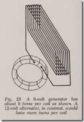
As will be presently explained, both these diffi culties are solved by connecting the coils to ad jacent commutator bars, Fig. 22. In an actual generator, each coil, instead of having one turn, has 8 or more, Fig. 23, in order to increase the voltage and current output. That is, 8 turns will give 8 times the voltage of one turn because 8 times as many lines of force are cut, and therefore provides 8 times the amperage of the single coil.
A typical generator armature with 20 coils of 8 turns each cannot be represented by the type of sketch shown in Fig. 23. The result would be nothing but a meaningless confusion of lines.
Therefore, we are forced to resort to the wiring diagram, Fig. 24, which shows that the ends of adjacent coils are connected to each other and also that each pair of coil ends is connected to a commutator bar. The commutator bars, of course, are insulated from each other. There are 8 loops in each coil in Fig. 24 to represent the 8 turns in the coil. Remember, however, that each of the 20 coils actually is arranged as shown in Fig. 23.
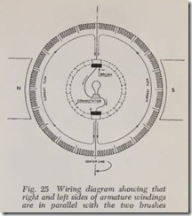
With the brushes located as shown in Fig. 24, the armature circuit is divided in two halves, left and right. These two halves are in parallel with the brushes. This statement will be clearer if we eliminate the commutator bars not in use, Fig. 25. It should be perfectly plain now that the left and right sides may be considered as separate circuits which are in parallel with the brushes.
It should be noted also that the coils in each half are in series. In either half, voltage is gen erated in all those coils which are cutting lines of force and the individual voltages add up to, let’s say, 15 volts across the brushes. Thus, in Fig. 25, current flows up through the two halves of the armature from the vieinity of the positive brush to the negative brush under a total pressure of 15 volts. Also this 15-volt pressure “across” the brushes drives the armature current out through the positive brush, thence through both external circuit and field circuits back to the negative brush.
As stated previously, the armature is a sort of fan which blows electrons through the circuit wires, the number of electrons which pass a given point each second being proportional to the amperes of current.
The brushes are thicker than the width of the commutator bars, therefore, a brush makes con tact with a new bar before it breaks contact with the preceding bar. Consequently the circuit re mains unbroken and sparking at the brushes is avoided-unless contact between brushes and commutator is interrupted by dirt, oil, commu tator roughness, weak brush springs, and/or stick ing brushes.
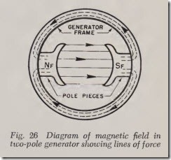
The magnetic field pro uced by the pole pieces alone is shown in Fig. 26 and the magnetic field produced by the armature alone is shown in Fig.27. NF and SF denote north and south magnetic poles (F stands for field). Likewise NA and SA indicates the fields produced by the armature. Remembering that like magnetic poles repel and unlike poles attract, NF attraets SA but repels NA with equal force. Similarly SF attracts NA but repels SA. Note that repulsion and attraction ex actly balance.
However, when the magnetic fields in Figs. 26 and 27 are combined, the lines of force in the resulting field is as shown .in Fig. 28. The com bined field is distorted in such a way that the forces of attraction are greater than the forces of repulsion, therefore, engine power is required to rotate the armature against the excess force of attraction (in a generator).
Just the opposite is true in an electric motor. In this case, distortion makes the forces of repulsion greater than the forces of attraction and it is this excess of repulsive magnetic force which rotates the armature. A generator will run as a motor if connected to a battery.
ELECTRIC MOTORS
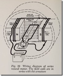
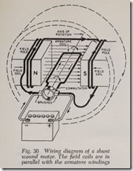
There are two common types of direct current electric motors, series wound and shunt wound. In a series wound motor, Fig. 29, the field coil windings and the armature windings are in series with each other whereas in a shunt wound motor the field coils are in parallel with the armature windings, Fig. 30.
The fan motor in an automobile heater, for example, is shunt wound because this type of winding gives a constant maximum speed because the field strength has a constant maximum value for a given voltage-say 15 volts. The speed of the fan may be reduced by introducing resistance in the field to reduce the number of amperes flowing through the field and thus cut down the field strength. The weaker the field, the slower the fan runs.
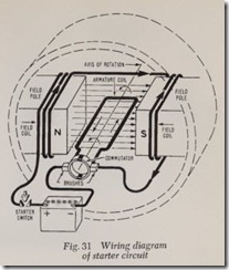
A starting motor is series wound because this type of winding provides maximum armature torque or turning effort at zero speed and this is just what is wanted to start the engine moving. When the starter switch is first closed, Fig. 31, the battery supplies a maximum of about 300 amperes ( 12-volt system) and this heavy current produces extremely powerful fields in both the field poles and the armature core. But after just a few sec onds the armature is up to its normal cranking speed and the amperage has dropped to about 150.
With a fully charged battery registering 12 volts, the battery voltage drops to 9 while the starter is in operation because the battery is un able to change its chemical energy fast enough to maintain 12 volts. However, 9 volts is adequate to force 150 amperes through the starter to drive the device at normal speed.
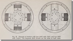
Automobile starters always have four poles in order to provide sufficiently powerful magnetic fields to produce adequate power for cranking the engine. On a few of the less expensive cars only two of the four poles have windings. The mag netic circuit, Fig. 32, is the same in both cases but naturally the fields are not quite as strong with only two poles wound as with four poles wound.
In a four-pole motor (or generator) there are two pairs of armature windings (instead of one pair for the two-pole machine illustrated in Figs. 29 and 30). Therefore, four brushes are required.
It is interesting to note that with 9 volts across the armature and a 150 ampere current flowing through the starter, the number of watts of power (watts equals voltage times amperage) absorbed by the starter is 9 times 150 or 1350 watts. One horsepower equals 746 watts. Therefore, the starter absorbs 1.8 hp of electrical energy. Deduc ing electrical and mechanical losses in the starter, the net horsepower available for cranking the engin e is about one and one half horsepower on the average car.
As explained in the chapter on Electricity, when current flows through a conductor, the conductor is heated. Therefore, all electrical apparatus must be designed with conductors of such size that the temperature rise is not only insufficient to melt the wire but not even sufficient to char the insulation. Therefore, all wires, whether within electrical units or whether connecting the various units in a circuit must be of sufficient size so that there is no danger of charring the insulation.
The size or capacity of an ignition coil, a voltage regulator, a starter or a generator, etc., are all designed with this temperature problem in view. For example, if it were not for the temperature
rise, a much smaller generator could be used for a 12-volt, 35-ampere output and likewise for starters and other electrical units.
In the case of the modern generator, its output is increased by including an air fan (at its driven end) which cools the field and armature coils with the result that increased amperes may be pro duced without harm to the insulation, Fig. 33.
In the 12-volt generator, field strength and number of armature conductors are both in creased without increasing the size of the gener ator. This is the most important factor in increas ing generator output, and is possible because finer wires can be used to carry 12-volt currents; more armature conductors can be put in the same space; more powerful field coils, wound with more turns of finer wire, can be placed in the same size frame as used for the old 6-volt generator.
In the case of 12-volt starters, the field coils are wound with finer wire, which increases field strength. More armature conductors, carrying slightly lower currents than its 6-volt counterpart, react with stronger magnetic fields to produce extra cranking power. In spite of the greater power output the 12-volt starters are about the same size as 6-volt units.
If by chance the current in a circuit becomes excessive because of a short circuit, a ground or excessive voltage, the circuit is often protected by a fuse or circuit breaker. The fuse is made of a low melting point metal which melts and breaks the circuit before damage is done to the insula tion. A circuit breaker is an electro-magnetic de vice whose points separate to break the circuit before amperage becomes high enough to injure the insulation.
Review Questions
|
1. |
What produces magnetism? …………………………………………….. . |
|
2. |
What is the difference between an electro magnet and a permanent magnet? ……….. . |
|
3. |
Name four· electromagnetic units in an automobile ……………………………. . |
|
4. |
What governs the strength of a magnetic field? …………………………….. . |
|
5. |
Magnetic lines of force can be made visible by what simple device? ………………. . |
|
6. |
Does a magnet have a definite polarity? ……………………………………. . |
|
7. |
In what direction do the lines of force move in the air gap between the poles of a horse- |
|
shoe magnet? ………………………………………………………… . |
|
|
8. |
In which way do the conductors in a generator armature move in relation to the lines of force of the field. . ……………,. ………………………………………. . |
|
9. |
Describe the construction of a simple generator. . ……………………………. . |
|
10. |
How are the magnetic lines of force produced in a generator field? ………………. . |
|
11. |
What does a commutator brush do in a generator? …………………………… . |
|
12. |
Field poles and armature cores are made out of what kind of material? …………… . |
|
13. |
What is residual magnetism? …………………………………………….. . |
|
14. |
What tends to resist armature rotation in a generator? …………………………. . |
|
15. |
What is a shunt generator? ……………………………………………. · · |
|
16. |
How does the number of individual coils and the number of windings in each coil on a gen- |
|
erator armature affect power output? ……………………………………… . |
|
|
17. |
To which two commutator bars is each end of any one armature coil fastened? ……… . |
|
18. |
How are the ends of each adjacent coil connected? …………………………… . |
|
19. |
What are two common types of direct current electric motors? ………………….. . |
|
20. |
What step had to be taken to increase generator capacity and starter torque on late model |
|
cars without increasing the size of these unitsP ………………………………. . |





![Fig.-21-When-20-armature-coils_thumb[2] Fig.-21-When-20-armature-coils_thumb[2]](http://machineryequipmentonline.com/electric-equipment/wp-content/uploads/2020/07/Fig.-21-When-20-armature-coils_thumb2_thumb.jpg)
![Fig.-22-In-an-actual-generator-the_t[2] Fig.-22-In-an-actual-generator-the_t[2]](http://machineryequipmentonline.com/electric-equipment/wp-content/uploads/2020/07/Fig.-22-In-an-actual-generator-the_t2_thumb.jpg)
![Fig.-24-Wiring-diagram-of-generator_[2] Fig.-24-Wiring-diagram-of-generator_[2]](http://machineryequipmentonline.com/electric-equipment/wp-content/uploads/2020/07/Fig.-24-Wiring-diagram-of-generator_2_thumb.jpg)
![Fig.-27-Diagram-of-magnetic-field-in[1] Fig.-27-Diagram-of-magnetic-field-in[1]](http://machineryequipmentonline.com/electric-equipment/wp-content/uploads/2020/07/Fig.-27-Diagram-of-magnetic-field-in1_thumb.jpg)
![Fig.-28-Resultant-magnetic-field_thu[1] Fig.-28-Resultant-magnetic-field_thu[1]](http://machineryequipmentonline.com/electric-equipment/wp-content/uploads/2020/07/Fig.-28-Resultant-magnetic-field_thu1_thumb.jpg)
![Fig. 33 This typical generator is air-cooled by a fan at¬_thumb[2] Fig. 33 This typical generator is air-cooled by a fan at¬_thumb[2]](http://machineryequipmentonline.com/electric-equipment/wp-content/uploads/2020/07/Fig.-33-This-typical-generator-is-air-cooled-by-a-fan-at%C2%AC_thumb2_thumb.jpg)