Moving Coil Loudspeaker
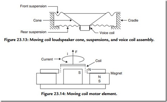
Figure 23.13 shows the structural features of a moving coil direct radiator loudspeaker, and for purposes of analysis it will be convenient to divide it into two parts: the “motor” or “drive” unit and the acoustic radiator, or diaphragm, described earlier.
The driving system consists of a solenoid situated in a radial magnetic field. It is free (within certain restraints) to move axially (see Figure 23.14). When a current is passed through the coil, a magnetic field will be generated, with the magnitude being directly proportional to //, and this will react with the steady field of the permanent magnet and a mechanical force will be developed that will tend to move the coil axially,
either inward or outward depending on the direction of the current. The magnitude of this force is
where B is flux density in Webers/m2,/is conductor length in meters, and/is current in amperes. It should be noted that l refers only to that portion of the coil situated in the magnetic field. As shown later, to reduce distortion the coil is often longer than the working magnetic field defined by the gap dimensions.
If the coil is free to move, its velocity will be determined by the applied force F and the mechanical impedance Zm. The mechanical impedance Zm will be a function of total mass (Lm) of the system, that is, voice coil and former, diaphragm, air loading, etc., resistance Rm due to losses in the suspension and radiation, and total stiffness (1/Cm) due to the restoring force.
Using normal circuit theory, the impedance will be
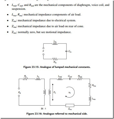
This represents a simple series resonant circuit shown in Figure 23.15. While one can predict resonant frequency from lumped mechanical constants, the analysis must be carried several stages further to arrive at the correct transfer characteristic from electrical input to sound output in practical loudspeaker design.
Figure 23.16 takes the analogue a stage further:


