Photodiodes
A photodiode is a type of photosensor in which the incident light falls on a semiconductor junction, and the separation of electrons and holes caused by the action of light will allow the junction to conduct even when it is reverse biased. Photodiodes are constructed like any other diodes, using silicon, but without the opaque coating that is normally used on signal and rectifier diodes. In the absence of this opaque coating, the material is trans- parent enough to permit light to affect the junction conductivity and so alter the amount of reverse current that flows when the diode is reverse- biased.
Because this is a reverse current diode, its amplitude is not large, and the sensitivity of photodiodes is quoted in terms of )lA of current per mWjcm2 of incident power. For the normal range of illuminations, this corresponds to currents of 1 nA to 1 mA at a reverse bias of -20 V. The lower figure is the dark current, the amount of current that flows with no perceptible illumination. As with all semiconductor devices, the dark current of a photo- diode will increase considerably as the temperature is increased, doubling for each 10oC rise in temperature.
Table 3.3 shows the characteristics of a typical silicon general-purpose photodiode from the RS Components catalogue. The peak spectral response is at 750 nm, which is in the near infrared, and the sensitivity is quoted as 0.7 )lAjmWjcm2. The typical dark current at a bias of -20 V is 1.4 nA, which means that the minimum detectable power input is of the order of 2 )lWjcm2.
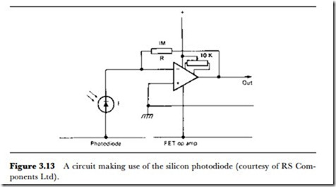
The current plotted against the illumination gives a reasonably linear graph, and the response time is around 250 ns, making the device suitable for modulated light beams that carry modulation into the video signal region. Figure 3.13 shows the suggested circuit for using this type of photo- diode along with an operational amplifier for a voltage output. The
feedback resistor R will determine the output voltage, which will be R x I, where I is the diode current. Note that when an operational amplifier is used in this way, the frequency response of the system is determined more by the operational amplifier and the stray capacitance across the feedback resistor than by the photodiode.
