Switching of Inductive Loads
It is important to remember that devices used for switching inductive loads may have to be de- rated if not designed for the purpose. This can be checked using the manufacturers documentation.
The de-rating factor to be applied is 0.8.
Example:
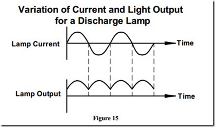
When discharge lighting is used where rotating machinery is present, there is a risk that rotating parts may appear to be stationary. This phenomenon is known as the “stroboscopic effect”. This effect occurs only where discharge lamps are installed. Discharge lamps illuminate and extinguish twice every cycle, in harmony with the alternating mains supply voltage.
The stroboscopic effect does not occur with incandescent lamp installations. Incandescent lamp filaments do not cool down fast enough to be affected by the mains cycle supply variation.
Examples of the stroboscopic effect can be seen when viewing old movies, where vehicle wheels may appear to be stopped or going in reverse. Flashing lights at discos also illustrate the stroboscopic effect.
The stroboscopic effect is also utilised by motor mechanics to set engine timing electronically. A strobe light is directed at the engine crank-shaft timing marks. With the engine running the crank-shaft timing marks appear to be stationary, thus allowing engine ignition timing adjustments to be made.
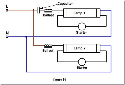
To overcome the problems associated with the stroboscopic effect, where rotating machinery is present, twin lamp fittings can be installed. These twin fittings are wired as a lead-lag circuit in such a manner that the current through the first lamp is out of synchronisation with current through the second lamp. This results in both lamps being extinguished at different time intervals during the AC cycle.
High frequency electronic ballasts are used in some fittings. These eliminate the stroboscopic effect as the operating frequency is 30,000 Hz.
Local incandescant lamps may also be used to eliminate this problem.
Figure 16 illustrates the internal wiring of a twin lamp fitting where one lamp is connected in series with a ballast whilst the other lamp is connected in series with a ballast and capacitor. This arrangement helps to eliminate the stroboscopic effect.
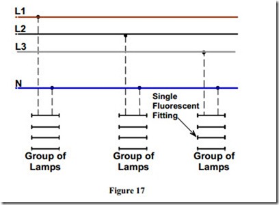
Figure 17 illustrates how the stroboscopic effect can be overcome with a lighting arrangement in industrial installations having three phase supplies. Adjacent lamps or alternate groups of lamps are connected between different phases and neutral. This arrangement also has the advantage of balancing the lighting load over the three phases and decreases the current flowing in the supply neutral.
Compact Fluorescent Lamps ( CFL )
Compact fluorescent lamps have become very common. These lamps are designed to replace the GLS lamp and the standard fluorescent tubes frequently used in domestic and small shop premises. Compact fluorescent lamps are available in a selection of designs and ratings. They can be used in any position. They usually have built in starting gear.
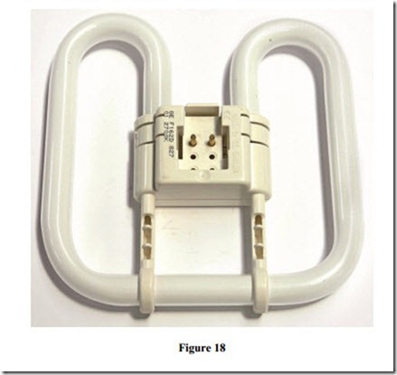
Figure 18 shows a 2D 16 Watt CFL. It has an equivalent light output to a 100 Watt GLS lamp. A 28 Watt and 38 Watt is also available. Its life expectancy is about 8000 hours. Cap type is GR10q. They are used for general lighting and emergency lighting applications.
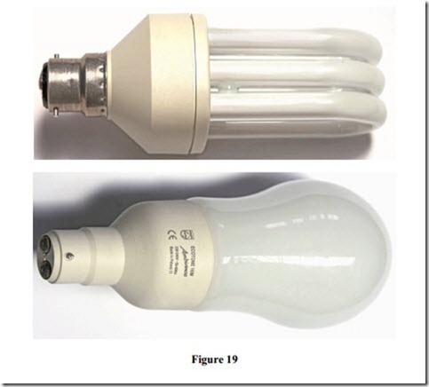
Figure 19 shows compact fluorescent lamps which can directly replace the standard BC incandescent lamp. They are now very popular in domestic situations. The initial cost of the lamp is high. They are slow to reach full brilliance so they are not suitable for situations where they would be switched on and off frequently. A 7 Watt provides the equivalent light output to a 60 Watt incandescent lamp.

