Grid Switches
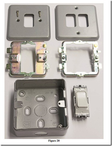
Figure 20 shows a one gang and a two gang grid cover plate, one gang and two gang grid plates, single switch box and grid switch. There must be an earth connection fitted between the switch box and grid plate.
Related posts:
Strain and pressure:Pressure gauges
Loudspeakers:Radiation of Sound
PROGRAMMABLE-LOGIC AND APPLICATION-SPECIFIC INTEGRATED CIRCUITS (PLASIC):FIELD-PROGRAMMABLE-LOGIC DE...
Other Digital Audio Devices:Transcribing a Recording by Computer
Transformer:Separation of Core Losses
Magnetism
Float switches:The Bubbler System
Basic troubleshooting principles:Tests for installation and troubleshooting
Electric Motor Manual – SELECTION AND APPLICATION – Special ac motors and their applicat...
INDUCTION MOTORS:THE EQUIVALENT CIRCUIT OF AN INDUCTION MOTOR
Troubleshooting de Motors
Switch principles:Contact resistance
Audio Amplifiers:Insulated Gate FETs (MOSFETs)
PERMANENT SPLIT-CAPACITOR MOTOR - SHADED-POLE MOTOR (Motor Starting Methods)
