Photoelectric Sensor
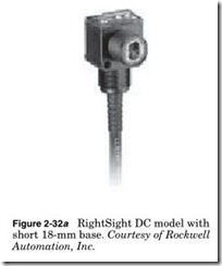
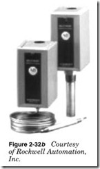
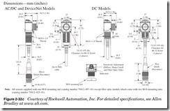
There are four basic components to any photosensor (Fig. 2-32a, b, c): light source, light detector, lenses, and output switching device. There are basically two types of photosensors: LED and photoelectric.
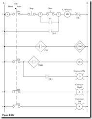
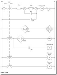
Shown in Fig. 2-32d:
Line 1 Terminal 1, contact of Hand/Off/Auto Selector switch closed in the hand position as indicated by the XOO, Normally Closed Stop button, terminal 2. Down one line, Normally Open Contact of M1 starter. Normally Open Start push button, terminal 3, motor starter with Normally Closed overload contact.
Line 2 Contact of control relay CR1.
Line 3 Output of photosensor PS1, solid-state relay SSR1.
Line 4 Contact of Hand/Off/Auto Selector switch closed in the Auto position as indicated by the OOX, Normally Closed contact of the solid-state relay SSR1. Down one line, green pilot light.
Line 5 Contact of Hand/Off/Auto Selector switch closed in the Hand position as indicated by the XOO, amber pilot light.
Line 6 Contact of Hand/Off/Auto Selector switch closed in the Off position as indicated by the OXO.
Figure 2-32d is a conveyor circuit:
Hand In the Hand position the Stop and start buttons can be used to operate the conveyor, and the amber pilot light will be on.
Off In the Off position the circuit is inactive and the red conveyor pilot light will be on.
Auto When the photo switch is actuated based on the presence of an object on the conveyor and the select switch is in the Auto position, the circuit is activated. The photo switch contacts are closed when the conveyor moves the object and turns on the green pilot light. When the object moves out of the sight of the photo switch, contacts open and the conveyor stops.
Caution should be taken when using solid-state devices. Do not short- circuit the output leads, as this can damage the unit. Also always check that the input voltage is within the range of the device.
Inductive Proximity Sensors
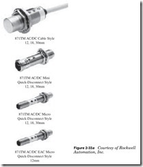
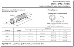
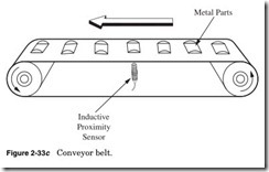
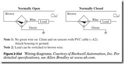
Inductive proximity sensors (Fig. 2-33a, b, c, d) are designed to operate by generating an electromagnetic field and detecting the eddy current losses generated when ferrous and nonferrous metal target objects enter the field. This means that the drop or change in the magnetic field trig- gers that sensor.
Shown in Fig. 2-33e:
Line 1 Terminal 1, contact of Hand/Off/Auto Selector switch closed in the Hand position as indicated by the XOO, Normally Closed Stop button, terminal 2. Down one line, Normally Open contact of M1 starter. Normally Open Start push button, terminal 3, motor starter with Normally Closed overload contact.
Line 2 Contact of control relay CR1.
Line 3 Output of inductive proximity sensor IPS1, solid-state relay SSR1.
Line 4 Contact of Hand/Off/Auto Selector switch closed in the Auto position as indicated by the OOX, Normally Open contact of the solid- state relay SSR1. Down one line, green pilot light.
Line 5 Contact of Hand/Off/Auto Selector switch closed in the Hand position as indicated by the XOO, amber pilot light.
Line 6 Contact of Hand/Off/Auto Selector switch closed in the Off position as indicated by the OXO.
Figure 2-33e is a conveyor circuit:
Hand In the Hand position the Stop and Start buttons can be used to operate the pump, and the amber pilot light will be on.
Off In the Off position the circuit is inactive, and the red conveyor pilot light will be on.
Auto When the proximity sensor switch is actuated based on the presence of an object on the conveyor and the select switch is in the Auto position, the circuit is activated. The proximity sensor switch contacts are closed when the conveyor moves the object and turns on the green pilot light. When the object moves out of the sight of the proximity sensor switch, contacts open and the conveyor stops.
Caution should be taken when using solid-state devices. Do not short- circuit the output leads as this can damage the unit. Also always check that the input voltage is within the range of the device.
Capacitive Proximity Sensors
Capacitive proximity sensors (Fig. 2-34a, b) are self-contained solid- state devices designed for noncontact sensing of a wide range of mate- rials. Unlike inductive proximity sensors, capacitive proximity sensors can detect nonmetal solids and liquids in addition to standard metal targets. They can even sense the presence of some targets through certain 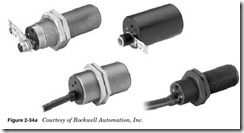
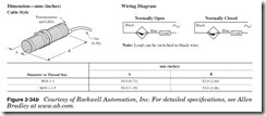
other materials, making them an ideal choice in some applications where inductive proximity and photoelectric sensors cannot be used.
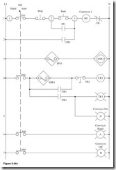
Shown in Fig. 2-34c:
Line 1 Terminal 1, contact of Hand/Off/Auto Selector switch closed in the Hand position as indicated by the XOO, Normally Closed Stop button, terminal 2. Down one line, Normally Open contact of M1 starter. Normally Open Start push button, terminal 3, motor starter with Normally Closed overload contact.
Line 2 Contact of control relay CR1.
Line 3 Output of inductive proximity sensor IPS1, solid-state relay SSR1.
Line 4 Contact of Hand/Off/Auto Selector switch closed in the Auto position as indicated by the OOX. Down one line, open contact of CR1. Down one line, open contact of CR1, time delay relay TR1. Down one line, green pilot light, Normally Open contact of the solid-state relay SSR1, Normally Closed time open contact of TR1, control relay CR1.
Line 6 Contact of Hand/Off/Auto Selector switch closed in the Hand position as indicated by the XOO, amber pilot light.
Line 7 Contact of Hand/Off/Auto Selector switch closed in the Off position as indicated by the OXO.
Figure 2-34c is a conveyor circuit:
Hand In the Hand position the Stop and Start buttons can be used to operate the conveyor, and the amber pilot light will be on.
Off In the Off position the circuit is inactive, and the red conveyor pilot light will be on.
Auto When the proximity sensor switch is actuated based on the presence of an object on the conveyor and the select switch is in the Auto position, the circuit is activated. The proximity sensor switch contacts are closed when the conveyor moves the object and turns on the green pilot light. The conveyor will continue to run for the time that is set by the TR1 relay or when the Selector switch is moved from the Auto position.
Caution should be taken when using solid-state devices. Do not short- circuit the output leads as this can damage the unit. Also always check that the input voltage is within the range of the device.
Limit Switches
There are an unlimited number of limit switches—too many for one book. (See Fig. 2-35a for a few of them.) Limit switches are activated by pressure for an object. They will have at least one contact Normally Open or Closed.
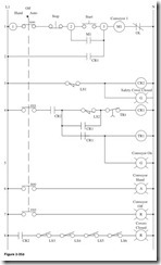
Shown in Fig. 2-35b: Drawing notes:
LS1—Operator safety cover limit switch. Normally Open held closed. Located at right lower side of the safety cover.
LS2—Box detected limit switch. Located above the conveyor center of platform. Normally Open.
LS3—Left cover. Located bottom right of cover. Normally Open. LS4—Right cover. Located bottom right of cover. Normally Open. LS5—Top cover. Located bottom left of cover. Normally Open. LS6—Bottom cover. Located bottom right of cover. Normally Open.
Line 1 Terminal 1, contact of Hand/Off/Auto Selector switch closed in the Hand position as indicated by the XOO, Normally Closed Stop button, terminal 2. Down one line, Normally Open contact of M1 starter. Normally Open Start push button, terminal 3, motor starter with Normally Closed overload contact.
Line 2 Contact of control relay CR1.
Line 3 LS1, control relay CR2.
Line 4 Contact of Hand/Off/Auto Selector switch closed in the Auto position as indicated by the OOX. Down one line, open contact of CR1. Down one line, open contact of CR1, time delay relay TR1. Down one line, green pilot light, Normally Open contact of limit switch LS2, Normally Closed time open contact of TR1, control relay CR1.
Line 6 Contact of Hand/Off/Auto Selector switch closed in the Hand position as indicated by the XOO, amber pilot light.
Line 7 Contact of Hand/Off/Auto Selector switch closed in the Off position as indicated by the OXO.
Line 8 Contact of CR2 Normally Open, Normally Open contact of limit switch LS3, Normally Open contact of limit switch LS4, Normally Open contact of limit switch LS5, Normally Open contact of limit switch LS6, red pilot light cover closed.
Figure 2-35b is an example of a conveyor circuit:
Hand In the Hand position the Stop and Start buttons can be used to operate the conveyor, and the amber pilot light will be on.
Off In the Off position the circuit is inactive, and the red conveyor pilot light will be on.
Auto The operator safety cover must be closed. When limit switch LS2 is actuated based on the presence of a box on the conveyor and the select switch is in the Auto position, the circuit is activated. The limit switch LS2 contacts are closed; the conveyor moves the object and turns on the green pilot light. The conveyor will continue to run for the time that is set by the TR1 relay or the Selector switch is moved from the Auto position.
