BPC (BATCH PROCESS CONTROL) CONTROLLERS
Batch process control (or batching control) is primarily used for repeated filling operations that lead to the production or the transport of finite quantities of material, by subjecting quantities of input materials to an ordered set of processing activities over a finite period and using one or more pieces of equipment. Batch control systems are also engineered to control, measure, and dispense any volume of liquid from drums, tanks, or other large storage vessel. Generally, they are used in any industry where batching, chemical packaging, or dilution is required to be accurate and efficient. For example, in the pharmaceutical and consumer products industries, batch control systems provide complete automation of batch processes including the mixing, blending, and reacting of products such as spice blends, dairy products, beverages, and personal care products.
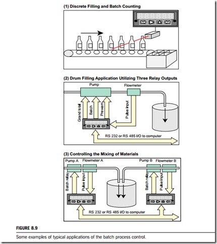
Typical batch applications include chemical packaging, waste-water treatment, machine manufacturing, pharmaceutical filling, and industrial plating. Figure 8.9 gives some examples of typical applications of batch control. As shown in the first example, the batch controller is ideal for discrete manufacturing as well as repetitive fill operations. Here, the batch controller counts bottles that it then groups into six-packs. Its control capability can be used to track bottles or six-packs. The second example is a drum-filling application, in which the batch controller utilizes its maximum of
three relays to control the pump. The prewarn relay slows down the pump near the preset to avoid overshoot. The batch relay stops the pump at the preset. The controller relay stops the filling operation once a predetermined number of drums have been filled. The third is for multiple-batch controllers that can be used in combination to control the mixing of materials in the proper ratio. Each feed line is equipped with its own pump, flow meter, and Laureate. Controller setup and monitoring of the mixing operation are facilitated by optional serial communications. An RS-232 or RS-485 I/O Interface allows a single data line to handle multiple controllers.
Batch control standards
Before the advent of industry-accepted standards for batch processing, every batch facility operated in its own world. Even something as basic as nomenclature was different in every plant. What might be called a “run” in one facility might be called a “batch” in another. What was a “formula” to one manager could be a “recipe” to another. Entire process methodologies varied just as widely. There were as many different ways to structure and run a batch as there were facilities in the world.
In 1995, ISA (The Instrumentation, Systems, and Automation Society) approved one of its first standards for batch processing, called ISA-88, or simply S88. These standards provided a framework for the design and operation of batch facilities, specifying terminology, process models, data structures and more.
Another standard, ISA-95 or S95, was developed in 2000. This standard is an outgrowth of the S88 standard, and commonly referred to as an international standard for developing an automated interface between enterprise and control systems.
The S88 and S95 standards have been widely accepted by the batch manufacturing community worldwide, which has allowed enterprises to improve communication, promote modularity, reduce maintenance costs and downtime, and improve overall performance. The savings can be substantial according to the ISA, plants using batch processing standards can save up to 30% of the cost of designing and implementing a batch processing system from scratch, and save domestic operations up to 15% of the cost of meeting the criteria for automation reliability.
(1) ANSI/ISA-88
ISA-88, or S88, is a standard that addresses batch process control that was approved by the ISA in 1995. It was adopted by the IEC in 1997 as IEC 61512-1. It is a design philosophy for describing equipment and procedures, and is equally applicable to manual processes. The current parts of the S88 standard include;
1. ANSI/ISA-88.01-1995 Batch Control Part 1: Models and terminology.
2. ANSI/ISA-88.00.02-2001 Batch Control Part 2: Data structures and guidelines for languages.
3. ANSI/ISA-88.00.03-2003 Batch Control Part 3: General and site recipe models and representation.
4. ANSI/ISA-88.00.04-2006 Batch Control Part 4: Batch Production Records.
S88 provides a consistent set of standards and terminology for batch control and defines the physical model, process model procedures, and recipes. Each of the processes in the model consists of an ordered set of stages which in turn consists of an ordered set of process operations made up of an ordered set of actions.
The physical model begins with the enterprise, which must contain a site which may contain areas which may contain process cells which must contain a unit which may contain equipment modules which may contain control modules. Some of these levels may be excluded, but not the unit.
The procedural control model consists of recipe procedures which consist of an ordered set of unit procedures which consist of an ordered set of operations which consist of an ordered set of phases. Some of these levels may be excluded.
Another fundamental issue was to separate recipes from equipment or equipment-independent recipes. This allowed the creation of agile and flexible batch manufacturing plants, where modularity and reuse of the recipes and elements that made up the plant equipment model could be defined and further developed into objects and libraries. Recipes could be either general, site, master, or control. The contents of the recipe include; header, formula, equipment requirements, procedure, and other information.
(2) ANSI/ISA-95
ISA-95 or S95 is an international standard for developing an automated interface between enterprise and control systems. This standard has been developed for global manufacturers, and can be applied in all industries, and in all sorts of processes, such as batch processes, continuous and repetitive processes. The objectives of ISA-95 are to provide consistent terminology for supplier and manu- facturer by means of consistent information and operations models, which are a foundation for clar- ifying application functionality and how information is to be used.
Within production areas, activities are executed and information is passed back and forth. The standard provides reference models for production activities, quality control activities, maintenance activities and inventory activities.
There are five parts of the ISA-95 standard, listed below:
1. ANSI/ISA-95.00.01-2000, Enterprise-Control System Integration Part 1: Models and Terminology consists of standard terminology and object models, which can be used to decide the information which should be exchanged.
2. ANSI/ISA-95.00.02-2001, Enterprise-Control System Integration Part 2: Object Model Attributes consists of attributes for every object that is defined in part 1. The objects and attributes of part 2 can be used for the exchange of information between different systems, but these objects and attributes can also be used as the basis for relational databases.
3. ANSI/ISA-95.00.03-2005, Enterprise-Control System Integration, Part 3: Models of Manufacturing Operations Management focuses on the functions and activities at level 3 (Production / MES layer; MES: Manufacture Execution System). It provides guidelines for describing and comparing the production levels of different sites in a standardized way.
4. ISA-95.04 Object Models & Attributes Part 4 of ISA-95: Object models and attributes for Manufacturing Operations Management. This technical specification defines object models that determine which information is exchanged between MES activities (which are defined in part 3 of ISA-95). The models and attributes from part 4 are the basis for the design and the implementation of interface standards and ensure flexible cooperation and information-exchange between the different MES activities.
5. ISA-95.05 B2M Transactions Part 5 of ISA-95: Business to Manufacturing Transactions. This technical specification defines operation between office and production automation systems, which can be used together with the object models of parts 1 and 2. The operations connect and organize the production objects and activities that are defined in earlier parts of the standard. Such operations take place on all levels within a business, but the focus of this technical specification lies on the interface between enterprise and control systems. On the basis of models, the operation will be described and the operation processing is logically explained.
Batch control systems
Most batch control systems provide automated process controls, including recipe development, batch management and execution, production scheduling, equipment performance monitoring, production history and material tracking functionalities. However, some batch control systems are also designed to improve batch scheduling, batch consistency and the automatic collection of real- time, reliable and accurate batch event data. This is because industry now needs to produce smaller batches of products with greater variation, quickly and efficiently. There are a range of batch control systems, designed and implemented using the ISA-88 standards and optimized using ISA-95 standards, to produce product batches repeatedly and consistently with minimum costs.
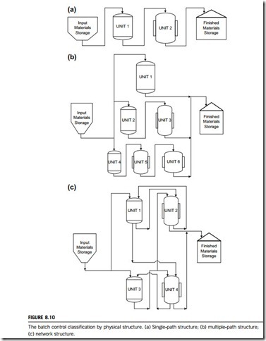
The architectures of batch control systems depend upon their physical structures. There are three classes of physical structure approved in the ANS/ISA-88.01-1995:
1. A single-path structure is a group of units through which a batch passes sequentially (see Figure 8.10(a)). A single-path structure could be a single unit, such as a reactor, or several units in sequence. Multiple input materials are typically used; multiple finished materials may be generated. Several batches may be in progress at the same time.
2. A multiple-path structure is shown in Figure 8.10(b). It consists of multiple single-path structures in parallel with no product transfer between them. The units may share raw material sources and product storage. Several batches may be in progress at the same time. Although units within a multiple-path structure may be physically similar, it is possible to have paths and units within a multipath structure that are of radically different physical design.
3. A network structure is shown in Figure 8.10(c). The paths may be either fixed or variable. When the paths are fixed, the same units are used in the same sequence. When the path is variable, the sequence may be determined at the beginning of the batch or it may be determined as the batch is being produced. The path could also be totally flexible. For example, a batch would not have to start at either Unit 1 or Unit 3; it could start with any unit and take multiple paths through the process cell. The units themselves may be portable within the process cell. In this case, verification of the process connections may be an important part of the procedures. Note that several batches may be in production at the same time. The units may share raw material sources and product storage.
A typical batch control system, regardless of physical structure, consists of the following components:
1. Field devices, such as sensors, actuators and instrumentation, that provide the batch control system with information and allow it to control the production process.
2. Batch controllers, such as special PLC, CNC, industrial computers or software packages, that receive the signals from the field devices and processes them according to pre-defined sequences in order to control actuators such as pumps, valves and motors.
3. Human machine interface as a system that allows interaction with the operators in the plant to monitor the status of the batch control system, to issue commands and to modify parameters.
4. Batch application, which visualizes and develops recipes.
With these components, all batch process control systems are capable of performing the following functions:
1. There must be an I/O interface between the processes and the control. The I/O interface passes all the information moving between the two parts of the total system.
2. The control system must provide continuous control functions to regulate appropriate portions of
the process.
3. The control system must provide sequential control functions. A properly designed batch control system should make it easy to describe the sequence of operations and the checks that must take place.
4. The control system must provide displays and interfaces which the operator can use to monitor and direct process activity.
In particular, if a batch control system is digital it should have additional functions:
1. A digital control system that allows the process to handle a range of products, and not just a single one.
The use of recipes is a concise and convenient method to describe the process steps for each product.
2. An advanced control system that provides a multiprogramming environment in which each specific task can be programmed in a simple stand-alone fashion. The system should also allow more than one unit in the plant to be controlled at the same time.
3. An advanced control system that provide displays which are oriented toward the total process rather than toward individual parameters.
4. An advanced control system that automatically detects and corrects process upsets and equipment failures.
5. An advanced control system that provides for device operations which reduce the complexity of the logic that the user must deal with. There are many mundane and repeated operations and error- checking functions which must be done where manipulating valves, pumps, motors, fans, and so on which can best be handled in device packages which standardize such operations.
Batch control mechanism
The mechanism for batch control depends on two factors; managing the batch processes, and handling recipes and batches.
(1) Managing batch processes
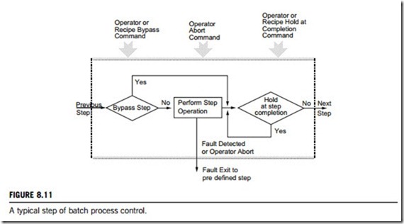
Batch processes deal with discrete quantities of raw materials or products. They allow more than one type of product to be processed simultaneously, as long as the products are separated by the equipment layout. They entail movement of discrete products from processing area to processing area. They have recipes (or processing instructions) associated with each load of raw material to be processed into product. They have more complex logic associated with processing than is found in continuous processes, and often include normal steps that can fail, and thus also include special steps to be taken in the event of a failure, which therefore gives exception handling in batch processes great importance.
Each step can be simple or complex in nature, consisting of one or more operations. Generally, once a step is started it must be completed to be successful. It is not uncommon to require some operator approval before leaving one step and starting the next. There is frequently provision for non-normal exits to be taken because of operator intervention, equipment failure, or the detection of hazardous conditions. Depending on the recipe for the product being processed, a step may be bypassed for some products. The processing operations for each step are generally under recipe control, but may be modified by operator override action. A typical process step is shown in Figure 8.11.
(2) Handling recipes and batches
Recipe and batch capability are standard requirements in many industries and applications. All batch control systems compatible with ISA-88 and ISA-95 standards should fully support batch and recipe handling, including recipe storage; automatic form filling; automatic batch creation and monitoring; and proof of process reporting. To perform the recipe and batch handling, the facilities below can be very helpful.
(1) Recipe data
Recipe data are a collection of control set-points that define the parameters required to make a specific product or to control a specific process. This handling allows any number of such recipes to be created, edited and called up via user-defined forms (such as in Microsoft Access format). These forms may display the recipe data and optionally allow items to be modified. They may also allow additional data to be entered that do not form part of the recipe but which may be required as part of the batch history.
(2) Batch data handler
The batch data handler is a database handler that makes it easy to handle the requirements of a batch process without the need to write programs or configuration scripts. The handler works by monitoring the system and watching for the occurrence of any of the criteria that have been defined as meaning that a batch is beginning. When the batch begins, it can reset selected signals and also store the values of any number of signals. As the batch progresses, the values of any number of
signals may be periodically written into the batch database, to keep a working record of how the batch is progressing. A batch ends when the conditions defining the end of the batch become true, such as a digital value going low, or a given expression evaluating to true. Again, data may be written to the batch database and signal values reset when the batch ends. It can also perform statistical surveys, calculating such values as mean, max, min, standard deviation, runtime, number of operations etc.
(3) Batch based trend recorder
In recipe and batch handling, all relevant parts of batches can be accessed from within historical trends where the start and end dates shown on the trend will be taken from the batch that has been selected. A tag substitution facility means that the same trend can be used to show data from different batches, even if those batches relate to different parts of the plant.
(4) Batch reporting
Proof of process reports may be generated automatically by a batch data handler or trend recorder when a batch ends. They may also be called up manually at any time. These reports, which are user-configurable, can display: (1) one off batch data such as Operator ID, batch run time, materials used, total product made etc.; (2) a list of all the alarms that occurred during the batch; (3) any number of trends each showing any number of signals. If there are too many data to display neatly on one batch report, the batch data recorder can be configured to run as many different reports as required.
In conclusion, the key points for recipe and batch handling are: (1) batches can be created manually or automatically; (2) facilities to continue an existing batch or start afresh; (3) any number of batches can be created; (4) full reporting, including multi-batch reporting, is dynamically feasible.
An integrated batch process controller
An integrated batch process controller, Simatic Batch, was developed by the Siemens AG in 2008. Simatic Batch is an industrial solution or batch control which; (1) is a high-level design solution able to integrate some distributed system (such as SCADA systems) into a batch control system; (2) it provides a batch control package as server/scheduler of the recipes, models, and tools compatible with the ISA-88.01 standard.
In fact, Simatic Batch plays a role as an integrated batch controller applied to a pre-defined PCS7 project with the required batch interface blocks and SFC blocks. Thus, each device in the control system is viewed as a complete object, that is, it is associated with a pre-defined set of I/O, is defined and controlled using CFC logic, and is visible on the SCADA as a single device with its alarms, real- time trends and information pop-ups. As such, once a project has been completed and commissioned, the user has complete control of the automation system without needing to modify the lower level control.
Simatic Batch provides special faceplates for controlling and monitoring plant units and equipment modules.
(1) Batch control center and batch planning
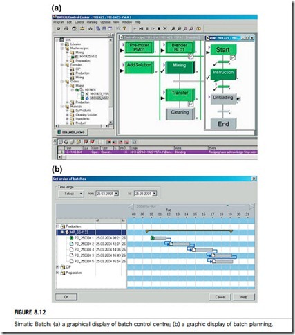
The batch control center is the “command center” for monitoring and controlling batch processes for Simatic Batch. Using the batch control center, it is possible to manage the data from a graphical user interface (see Figure 8.12(a)). It offers powerful functions including:
1. reading in and updating the plant data of the basic automation;
2. defining user privileges for all functions, for clients, or for plant units of Simatic Batch;
3. management of master recipes, and starting the recipe editor in order to enter the recipe structure;
4. exporting and importing of basic recipes, formulas and library objects;
5. creation of batches with master recipes; starting of batch processing and controlling of batches;
6. monitoring and diagnostics of batch processing and recording and archiving of recipes and batch data.
The batch control center enables the creation of individual production orders and batches. A greatly increased planning functionality is offered by the batch planning option package with which the batches can be planned in advance for a large number of production orders.
In addition to planning, the scope of functions include the modification, cancellation, deletion and enabling of batches. Creation and distribution of the batches for a production order are possible manually, but can also be carried out automatically depending on the definition of the batch number or production quantity. All batches and their occupation of plant units can be clearly presented in a combination of Gantt diagram and table, as shown in Figure 8.12(b). Time conflicts or conflicts resulting from multiple occupation of plant units are identified by symbols. Such conflicts can be eliminated simply by shifting the associated batches in the Gantt diagram.
(2) Recipe editor and batch report
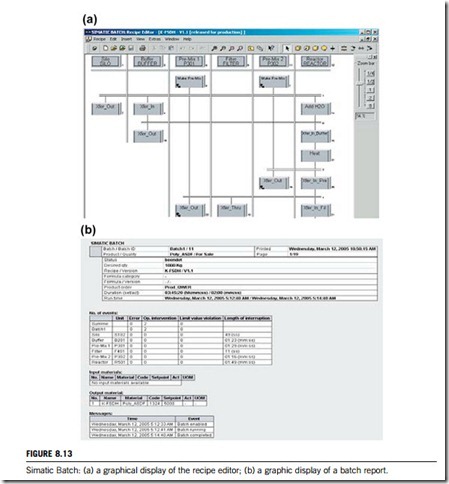
The recipe editor is a user-friendly tool for the easy, intuitive creation and modification of basic recipes. It has a graphical user interface, as shown in Figure 8.13(a), processing functions for individual and grouped objects, and a structural syntax check. The basis for recipe creation is the batch objects created from the batch plant configuration using the Simatic PCS7 engineering system, e.g. plant units and technological functions. The following tasks can be performed with the recipe editor:
1. creation of new basic recipes and library operations;
2. querying of statuses of the recipe objects and of process values in transition conditions;
3. documentation of basic recipes;
4. selection of plant unit candidates through limitation of equipment properties;
5. releasing basic recipes for test or production;
6. configuring arithmetic expressions for calculating set-points for transitions and recipe parameters from recipe variables and constants.
The batch report function integrated in the recipe editor is used to produce recipe and batch reports. These reports (an example is given in Figure 8.13(b)) contain all data required for reproduction of the batch process, for proof of the quality, and for compliance with statutory directives. These include, for example: identification data; control recipe data; effective production data; time sequence of steps; status messages, fault messages and alarms; operator interventions; process values.
(3) Hierarchical and plant-unit neutral recipes
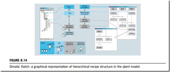
Simatic Batch provides a functional unit that fully covers the models described in the ISA-88.01 standard. The hierarchical recipe structure is mapped on the plant module as follows:
1. recipe procedure for controlling the process or the production in a plant;
2. partial recipe procedure for controlling a process step in a plant unit;
3. recipe operation/function for the process engineering task/function in an equipment module.
Creation of a recipe which is neutral to the plant unit minimizes the engineering overhead and provides significant advantages for validation. During creation of the recipe, the partial recipe procedures are
only assigned plant unit classes. The final assignment of plant units is only carried out at run-time. In the cases of batches which run for a longer period and where the plant units are not to be already determined and occupied at the start of a batch, the assignment is only carried out at the time of use. Conflicts in the occupation of plant units are detected by the system, and displayed. Figure 8.14 is a representation of hierarchical recipe structure in the plant model.
The following occupation strategies for plant unit assignments permit optimum orientation according to the special plant situation. It ought to noted that the occupation strategy can also be modified during the batch run-time, just like plant unit assignment.
1. “Manual selection of plant unit” for preselection at time of recipe creation.
2. “Preferred plant unit” for preselection at time of recipe creation.
3. Determination of “plant unused for longest time” to achieve uniform utilization.
4. Assignment of plant unit to be used by means of “process parameters” from an external module (e.g. scheduler).
