PROGRAMMABLE LOGIC CONTROLLERS
A very popular type of controller used in industry and process control is a specialized computer called a programmable logic controller (PLC), or programmable controller. It uses sensors to monitor physical variables and generates output control signals to operate heating elements, motors, pumps, solenoids, and other devices. The PLC, however, contains a microprocessor that can be
programmed in a special language that permits the PLC to be customized to the particular control function. In this way, a standard PLC can be programmed and configured for virtually any application. The PLC is by far one of the most popular and versatile control devices in use in industry.
The main function of a PLC is factory automation. It is a versatile special- purpose computer that can be quickly and easily reconfigured to meet changes
and additions in factories, plants, and other operations that routinely need to control and sequence various machines and processes. While an embedded controller or personal computer could be used in some operations, they are harder to pro- gram and apply and are less flexible when rapid changes are needed. Furthermore, these common microcomputers are not designed for the factory environment. But PLCs are rugged and hardened against the harsh environment of most factories and plants. They can withstand the temperature ranges, vibration, and dirty conditions usually existing in a manufacturing or process control setting.
Organization
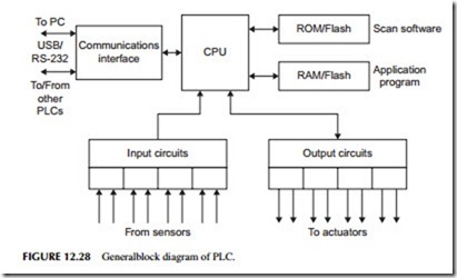
A general block diagram of a PLC is shown in Figure 12.28. It is like most other microcomputer diagrams but there are some differences. A microproces- sor is at the heart of the design. This CPU is coupled to a ROM where a special control program is stored. This program implements the basic scan operational mode of the PLC. RAM is also available to store the application program. Flash memory may also be used in place of RAM.
The key to the PLC’s versatility is its extensive I/O section. It has a variety of input and output modules. These are fixed in small, single-function PLCs, but in the larger more flexible units, the PLC is designed to accept a wide variety of separate I/O modules. These usually plug into a rack containing the main PLC unit and power supply. The different I/O modules let the user customize the PLC to the specific application.
Some examples of I/O modules are digital inputs and outputs with common logic levels or conditioned levels, analog-input modules that accept analog signals from sensors, and analog output modules that generate analog out- puts for controlling actuators of almost any kind. A huge variety is available.
A communications interface is also available so that the PLC can talk to external devices like a PC or other PLCs that are connected to form a larger control system. RS-232 and RS-485 serial interfaces are common as is USB. The pro- gram describing the operations to be implemented is developed on an external PC, and then downloaded to the PLC RAM or flash memory via the USB or RS-232 interfaces.
Operation
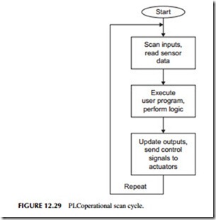
The general operation of a PLC is shown in Figure 12.29. When the PLC is started, the internal operational program looks at the application program and interprets what is to be done. The sequence of operations is to first scan the inputs. The PLC looks at what the various sensors are doing. It gets a status update from the application itself. The program then interprets what to do next based on the application program. It processes the input to determine what the outputs should be. Then it updates the outputs to carry out the application. Then the cycle repeats itself at a high rate of speed. The inputs are scanned and outputs updated every 1 millisecond or so, slower or faster as the application requires.
A simple example is using a switch to turn on a motor. The switch contacts are connected to an input module by wires. Output wires connect to a relay that in turn is used to operate the motor. As the PLC is scanning, it sees that the switch is off, so it does nothing. But as soon as the switch is turned
on, the next scan detects this new condition. The program then tells the CPU that if the switch is on, turn on the relay. An output signal is sent to the output module, which then actuates an external relay. The relay contacts then turn the motor on. If the switch is then turned off, the next scan detects this condition and causes the output to turn off the relay and motor.
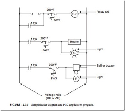
As for programming, PLCs can be programmed in various ways. Most PLC vendors have special languages to do the programming. In some cases, standard BASIC or C languages may be used. One widely used approach is a graphical language called ladder logic. Ladder logic is the technology that the PLC replaced decades ago. Control systems were made with relays, and they were wired so the diagram looked like a ladder (see Figure 12.30). The two vertical lines represent a DC or AC voltage source. Circuits are then connected between these two “rails,” forming rungs on the ladder. The circuits are connections of switches, relays, and other components. The software allows the user to build the ladder logic program on the screen, while a translation pro- gram in the PC converts it into the binary code that the PLC can execute.
This particular circuit in Figure 12.30 does the following: when the ON pushbutton is pressed, current is applied to relay coil 1CR through normally closed contacts of SW1. SW1 is a thermal switch whose contacts stay closed as long as the temperature is less than 300 degrees Fahrenheit (300°F). If the temperature rises above that level, the contacts open, thereby breaking the circuits. Relay contacts 1CR around the ON pushbutton latch the circuit on when the ON pushbutton is released.
In the next “rung” of the ladder contacts 1CR are on the relay. They close when the relay turns on. This applies voltage to a heating element. This current flows through the normally closed contacts of thermal switch SW2. A green light in parallel with the heating elements turns on to indicate the heater is on.
When the heater temperature reaches 200°F, SW2 opens, turning off the heater and the green light. As the heater cools, SW2 will then close again, applying voltage to the heater. The heater will then cycle off and on keeping its temperature near the 200°F value.
If the temperature should rise above 300°F due to a failure of SW2 °F then SW1 opens. Relay 1CR is turned off, and its contacts open, releasing the latch on rung 1 and opening the circuit on rung 2. Thermal switch SW3 closes at 300°F, turning on a red light and ringing an alarm bell.
This example could be programmed with a graphical ladder logic program or with special commands and syntax of a traditional programming language.
In addition to being able do simple off/off tasks common to industrial control, special hardware in the PLC can also implement counters and timers so that external events can be counted and the sequencing of events can be programmed.
