THE ROTATING MAGNETIC FIELD
Before we look at how the rotating field is produced, we should be clear what it actually is. Because both the rotor and stator iron surfaces are smooth (apart from the regular slotting), and are separated by a small air gap, the flux produced by the stator windings crosses the air gap radially. The behaviour of the motor is dictated by this radial flux, so we will concentrate first on establishing a mental picture of what is meant by the ‘flux wave’ in an induction motor.
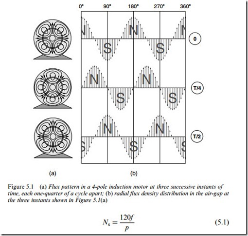
The pattern of flux in an ideal 4-pole induction motor supplied from a balanced 3-phase source is shown in Figure 5.1(a). The top sketch corresponds to time t ¼ 0; the middle one shows the flux pattern one quarter of a cycle of the mains supply later (i.e. 5 ms if the frequency is 50 Hz) and the lower one corresponds to a further quarter cycle later. fie note that the pattern of flux lines is repeated in each case, except that the middle and lower ones are rotated by 458 and 908, respectively, with respect to the top sketch.
The term ‘4-pole’ reflects the fact that the flux leaves the stator from two N poles, and returns at two S poles. Note, however, that there are no physical features of the stator iron mark it out as being 4-pole, rather than say 2-pole or 6-pole. As we will see, it is the layout and intercon- nection of the stator coils that sets the pole number.
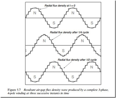
If we plot the variation of the radial air-gap flux density with respect to distance round the stator, at each of the three instants of time, we get the patterns shown in Figure 5.1(b). The first feature to note is that the radial flux density varies sinusoidally in space. There are two N peaks and two S peaks, but the transition from N to S occurs in a smooth sinusoidal way, giving rise to the term ‘flux wave’. The distance from the centre of one N pole to the centre of the adjacent S pole is called the pole-pitch, for obvious reasons.
Staying with Figure 5.1(b), we note that after one quarter of a cycle of the mains frequency, the flux wave retains its original shape, but has moved round the stator by half a pole-pitch, while after half a cycle it has moved round by a full pole-pitch. If we had plotted the patterns at intermediate times, we would have discovered that the wave maintained a constant shape, and progressed smoothly, advancing at a uniform rate of two pole-pitches per cycle of the mains. The term ‘travelling flux wave’ is thus an appropriate one to describe the air-gap field.
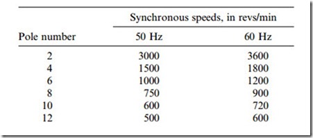
For the 4-pole wave here, one complete revolution takes two cycles of the supply, so the speed is 25 rev/s (1500 rev/min) with a 50 Hz supply, or 30 rev/s (1800 rev/min) at 60 Hz. The general expression for the speed of the field (which is known as the synchronous speed) Ns, in rev/min is
where p is the pole number. The pole number must be an even integer, since for every N pole there must be a S pole. Synchronous speeds for commonly used pole numbers are given in the table below.
fie can see from the table that if we want the field to rotate at inter- mediate speeds, we will have to be able to vary the supply frequency, and this is what happens in inverter-fed motors, which are dealt in Chapter 8.
Production of rotating magnetic field
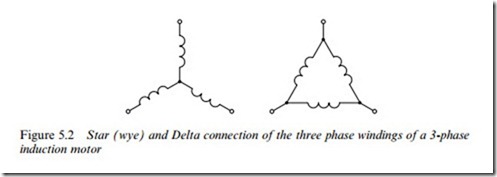
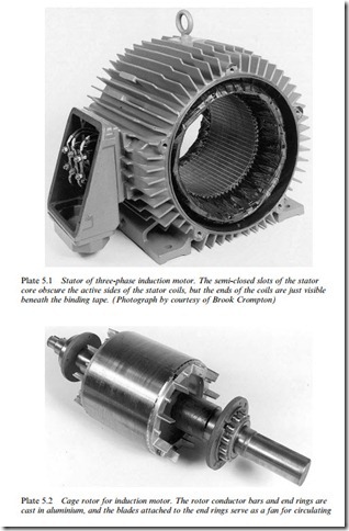
Now that we have a picture of the field, we turn to how it is produced. If we inspect the stator winding of an induction motor we find that it consists of a uniform array of identical coils, located in slots. The coils are in fact connected to form three identical groups or phase windings, distributed around the stator, and symmetrically displaced with respect to one another. The three-phase windings are connected either in star (wye) or delta (mesh), as shown in Figure 5.2.
The three-phase windings are connected directly to a three-phase a.c.
supply, and so the currents (which produce the MMF that sets up the flux) are of equal amplitude but diVer in time phase by one-third of a cycle (1208), forming a balanced three-phase set.
Field produced by each phase winding
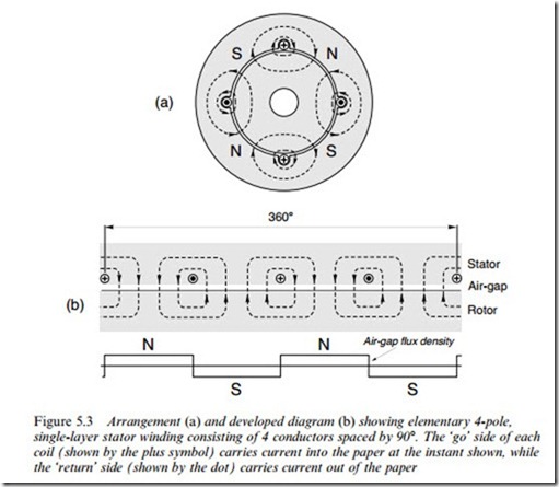
The aim of the winding designer is to arrange the layout of the coils so that each phase winding, acting alone, produces an MMF wave (and hence an air-gap flux wave) of the desired pole number, and with a sinusoidal variation of amplitude with angle. Getting the desired pole number is not diYcult: we simply have to choose the right number and pitch of coils, as shown by the diagrams of an elementary 4-pole winding in Figure 5.3.
In Figure 5.3(a) we see that by positioning two coils (each of which spans one pole-pitch) 1808 apart we obtain the correct number of poles (i.e. 4). However, the air-gap field – shown by only two flux lines per pole for the sake of clarity – is uniform between each go and return coil side, not sinusoidal.
A clearer picture of the air-gap flux wave is presented in the developed view in Figure 5.3(b), where more equally spaced flux lines have been added to emphasise the uniformity of the flux density between the go and return sides of the coils. Finally, the plot of the air-gap flux density underlines the fact that this very basic arrangement of coils produces a rectangular flux density wave, whereas what we are seeking is a sinusoidal wave.
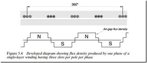
fie can improve matters by adding more coils in the adjacent slots, as shown in Figure 5.4. All the coils have the same number of turns, and carry the same current. The addition of the extra slightly displaced coils gives rise to the stepped waveform of MMF and air-gap flux density shown in Figure 5.4. It is still not sinusoidal, but is much better than the original rectangular shape.
It turns out that if we were to insist on having a perfect sinusoidal flux density waveform, we would have to distribute the coils of one phase in a smoothly varying sinusoidal pattern over the whole periphery of the stator. This is not a practicable proposition, firstly because we would
also have to vary the number of turns per coil from point to point, and secondly because we want the coils to be in slots, so it is impossible to avoid some measure of discretisation in the layout. For economy of manufacture we are also obliged to settle for all the coils being identical, and we must make sure that the three identical phase windings fit together in such a way that all the slots are fully utilised.
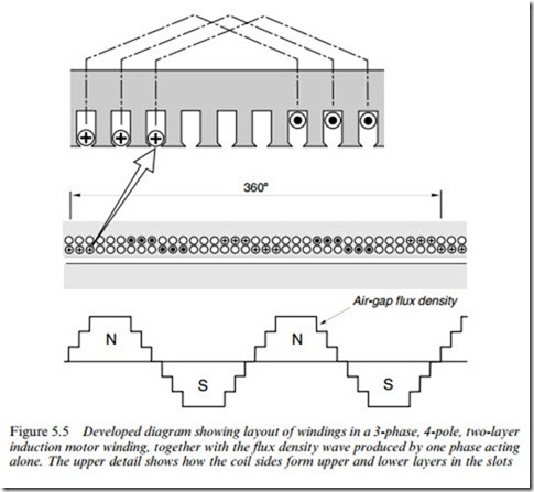
Despite these constraints we can get remarkably close to the ideal sinusoidal pattern, especially when we use a ‘two-layer’ winding. A typical arrangement of one phase is shown in Figure 5.5. The upper expanded sketch shows how each coil sits with its go side in the top of a slot while the return side occupies the bottom of a slot rather less than one pole-pitch away. Coils which span less than a full pole-pitch are known as short-pitch or short-chorded: in this particular case the coil pitch is six slots, the pole-pitch is nine slots, so the coils are short-pitched by three slots.
This type of winding is almost universal in all but small induction motors, the coils in each phase being grouped together to form ‘phase- bands’ or ‘phase-belts’. Since we are concentrating on the field produced by only one of the phase windings (or ‘phases’), only one- third of the coils in Figure 5.5 are shown carrying current. The remain- ing two-thirds of the coils form the other two phase windings, as discussed in Section 5.2.3.
Returning to the flux density plot in Figure 5.5 we see that the eVect of short-pitching is to increase the number of steps in the waveform, and that as a result the field produced by one phase is a fair approximation to a sinusoid.
The current in each phase pulsates at the supply frequency, so the field produced by, say, phase A, pulsates in sympathy with the current in phase A, the axis of each ‘pole’ remaining fixed in space, but its polarity
changing from N to S and back once per cycle. There is no hint of any rotation in the field of one phase, but when the fields produced by each of the three-phases are combined, matters change dramatically.
Resultant field
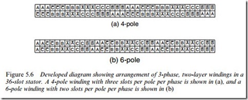
The layout of coils for the complete 4-pole winding is shown in Figure 5.6(a). The go sides of each coil are represented by the capital letters (A, B, C) and the return sides are identified by bars over the letters (A, B, C). (For the sake of comparison, a 6-pole winding layout that uses the same stator slotting is shown in Figure 5.6(b): here the pole- pitch is six slots and the coils are short-pitched by one slot.)
Returning to the 4-pole winding, we can see that the windings of phases B and C are identical with that of phase A apart from the fact that they are displaced in space by plus and minus two-thirds of a pole- pitch respectively.
Phases B and C therefore also produce pulsating fields, along their own fixed axes in space. But the currents in phases B and C also diVer in time phase from the current in phase A, lagging by one-third and two- thirds of a cycle, respectively. To find the resultant field we must there- fore superimpose the fields of the three phases, taking account not only of the spatial diVerences between windings, but also the time diVerences between the currents. This is a tedious process, so the intermediate steps have been omitted and instead we move straight to the plot of the resultant field for the complete 4-pole machine, for three discrete times during one complete cycle, as shown in Figure 5.7.
fie see that the three pulsating fields combine beautifully and lead to a resultant 4-pole field, which rotates at a uniform rate, advancing by two pole-pitches for every cycle of the mains. The resultant field is not exactly sinusoidal in shape (though it is actually more sinusoidal than the field produced by the individual phase windings), and its shape varies a little from instant to instant; but these are minor worries. The resultant field is amazingly close to the ideal travelling wave and yet the winding layout is simple and easy to manufacture. This is an elegant engineering achievement, however one looks at it.
Direction of rotation
The direction of rotation depends on the order in which the currents reach their maxima, i.e. on the phase-sequence of the supply. Reversal of direction is therefore simply a matter of interchanging any two of the lines connecting the windings to the supply.
Main (air-gap) flux and leakage flux
Broadly speaking the motor designer shapes the stator and rotor teeth to encourage as much as possible of the flux produced by the stator to pass
right down the rotor teeth, so that before completing its path back to the stator it is fully linked with the rotor conductors (see later) which are located in the rotor slots. fie will see later that this tight magnetic coupling between stator and rotor windings is necessary for good running performance, and the field which provides the coupling is of course the main or air-gap field, which we are in the midst of discussing.
In practice the vast majority of the flux produced by the stator is indeed main or ‘mutual’ flux. But there is some flux which bypasses the rotor conductors, linking only with the stator winding, and known as stator leakage flux. Similarly not all the flux produced by the rotor currents links the stator, but some (the rotor leakage flux) links only the rotor conductors.
The use of the perjorative-sounding term ‘leakage’ suggests that these leakage fluxes are unwelcome imperfections, which we should go out of our way to minimise. However, whilst the majority of aspects of performance are certainly enhanced if the leakage is as small as possible, others (notably the large and unwelcome current drawn from the mains when the motor is started from rest) are made much worse if the coupling is too good. So we have the somewhat paradoxical situation in which the designer Wnds it comparatively easy to layout the windings to produce a good main Xux, but is then obliged to juggle the detailed design of the slots to obtain just the right amount of leakage Xux to give acceptable all-round performance.
The weight which attaches to the matter of leakage Xux is reXected in the prominent part played by the associated leakage reactance in equiva- lent circuit models of the induction motor, and is discussed in Chapter 7. However, such niceties are of limited importance to the user, so in this and the next chapters we will limit references to leakage reactance to well-deWned contexts, and in general, where the term ‘Xux’ is used, it will refer to the main air-gap Weld.
Magnitude of rotating flux wave
We have already seen that the speed of the Xux wave is set by the pole number of the winding and the frequency of the supply. But what is it that determines the amplitude of the Weld?
To answer this question we can continue to neglect the fact that under normal conditions there will be induced currents in the rotor. We might even Wnd it easier to imagine that the rotor conductors have been removed altogether: this may seem a drastic assumption, but will prove justiWed later. The stator windings are assumed to be connected to a balanced 3-phase a.c. supply so that a balanced set of currents Xows in the windings. We denote the phase voltage by V, and the current in each phase by Im, where the subscript m denotes ‘magnetising’ or Xux- producing current.
From the discussion in Chapter 1, we know that the magnitude of the Xux wave (Bm) is proportional to the winding MMF, and is thus pro- portional to Im. But what we really want to know is how the Xux density depends on the supply voltage and frequency, since these are the only two parameters over which we have control.
To guide us to the answer, we must Wrst ask what eVect the travelling Xux wave will have on the stator winding. Every stator conductor will of course be cut by the rotating Xux wave, and will therefore have an e.m.f. induced in it. Since the Xux wave varies sinusoidally in space, and cuts each conductor at a constant velocity, a sinusoidal e.m.f. is induced in each conductor. The magnitude of the e.m.f. is proportional to the magnitude of the Xux wave (Bm), and to the speed of the wave (i.e. to the supply frequency f ). The frequency of the induced e.m.f. depends on the time taken for one N pole and one S pole to cut the conductor. We have already seen that the higher the pole number, the slower the Weld rotates, but we found that the Weld always advances by two pole-pitches for every cycle of the mains. The frequency of the e.m.f. induced in the stator conductors is therefore the same as the supply frequency, regard- less of the pole number. (This conclusion is what we would have reached intuitively, since we would expect any linear system to react at the same frequency at which we excited it.)
The e.m.f. in each complete phase winding (E) is the sum of the e.m.f.’s in the phase coils, and thus will also be at supply frequency. (The alert reader will realise that whilst the e.m.f. in each coil has the same magnitude, it will diVer in time phase, depending on the geomet- rical position of the coil. Most of the coils in each phase band are close together, however, so their e.m.f.’s – though slightly out of phase – will more or less add up directly.)
If we were to compare the e.m.f.’s in the three complete phase windings, we would Wnd that they were of equal amplitude, but out of phase by one-third of a cycle (1208), thereby forming a balanced 3-phase set. This result could have been anticipated from the overall symmetry. This is very helpful, as it means that we need only consider one of the phases in the rest of the discussion.
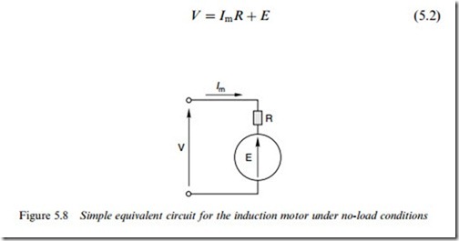
So we Wnd that when an alternating voltage V is applied, an alternat- ing e.m.f., E, is induced. We can represent this state of aVairs by the a.c. equivalent circuit for one phase shown in Figure 5.8.
The resistance shown in Figure 5.8 is the resistance of one complete phase winding. Note that the e.m.f. E is shown as opposing the applied voltage V. This must be so, otherwise we would have a runaway situ- ation in which the voltage V produced the magnetising current Im which in turn set up an e.m.f. E, which added to V, which further increased Im and so on ad inWnitum.
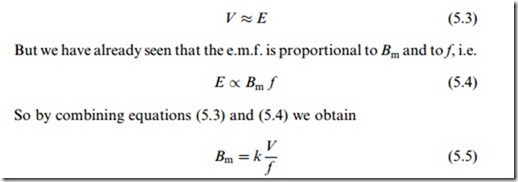
We Wnd in practice that the term ImR (which represents the volt drop due to winding resistance) is usually very much less than the applied voltage V. In other words most of the applied voltage is accounted for by the opposing e.m.f., E. Hence, we can make the approximation
where the constant k depends on the number of turns per coil, the number of coils per phase and the distribution of the coils.
Equation (5.5) is of fundamental importance in induction motor
operation. It shows that if the supply frequency is constant, the Xux in the air-gap is directly proportional to the applied voltage, or in other words the voltage sets the Xux. We can also see that if we raise or lower the frequency (to increase or reduce the speed of rotation of the Weld), we will have to raise or lower the voltage in proportion if, as is usually the case, we want the magnitude of the Xux to remain constant.
It may seem a paradox that having originally homed-in on the mag- netising current Im as being the source of the MMF which in turn produces the Xux, we Wnd that the actual value of the Xux is governed only by the applied voltage and frequency, and Im does not appear at all in equation (5.5). We can see why this is by looking again at Figure 5.8 and asking what would happen if, for some reason, the e.m.f. E were to reduce. We would Wnd that Im would increase, which in turn would lead to a higher MMF, more Xux, and hence to an increase in E. There is clearly a negative feedback eVect taking place, which continually tries to keep E equal to V. It is rather like the d.c. motor (see Chapter 3) where the speed of the unloaded motor always adjusted itself so that the back e.m.f. equalled the applied voltage. Here, the magnetising current always ad- justs itself so that the induced e.m.f. is almost equal to the applied voltage.
Needless to say this does not mean that the magnetising current is arbitrary, but to calculate it we would have to know the number of turns in the winding, the length of the air-gap (from which we could calculate the gap reluctance) and the reluctance of the iron paths. From a user point of view there is no need to delve further in this direction. We should however recognise that the reluctance will be dominated by the air-gap, and that the magnitude of the magnetising current will therefore depend mainly on the size of the gap. The larger the gap, the bigger the magnetising current. Since the magnetising current contributes to stator copper loss, but not to useful output power, we would like it to be as small as possible, so we Wnd that induction motors usually have the smallest air-gap, which is consistent with providing the necessary mech- anical clearances. Despite the small air-gap the magnetising current can be appreciable: in a 4-pole motor, it may be typically 50% of the full- load current, and even higher in 6-pole and 8-pole designs.
Excitation power and VA
The setting up of the travelling wave by the magnetising current amounts to the provision of ‘excitation’ for the motor. Some energy is stored in the magnetic Weld, but since the amplitude remains constant once the Weld has been established, no power input is needed to sustain the Weld. We therefore Wnd that under the conditions discussed so far, i.e. in the absence of any rotor currents, the power input to the motor is very small. (We should perhaps note that the rotor currents in a real motor are very small when it is running light, so the hypothetical situation we are looking at is not so far removed from reality as we may have supposed.)
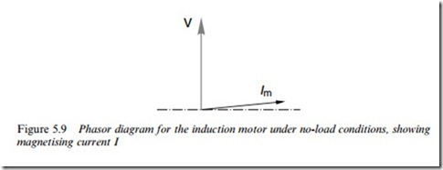
Ideally the only source of power losses would be the copper losses in the stator windings, but to this must be added the ‘iron losses’ which arise from eddy currents and hysteresis in the laminated steel cores of rotor and stator. However, we have seen that the magnetising current can be quite large, its value being largely determined by the air-gap, so we can expect an unloaded induction motor to draw appreciable current from the supply, but very little real power. The VA will therefore be substantial, but the power factor will be very low, the magnetising current lagging the supply voltage by almost 908, as shown in the phasor diagram (see Figure 5.9).
Viewed from the supply the stator looks more or less like a pure inductance, a fact which we would expect intuitively given that – having ignored the rotor circuit – we are left with only an arrangement of Xux-producing coils surrounded by a good magnetic circuit. This matter is explored further in Chapter 7.
Summary
When the stator is connected to a 3-phase supply, a sinusoidally distributed, radially directed rotating magnetic Xux density wave is set up in the air-gap. The speed of rotation of the Weld is directly proportional to the frequency of the supply, and inversely proportional to the pole number of the winding. The magnitude of the Xux wave is proportional to the applied voltage, and inversely proportional to the frequency.
When the rotor circuits are ignored (i.e. under no-load conditions), the real power drawn from the mains is small, but the magnetising current itself can be quite large, giving rise to a signiWcant reactive power demand from the mains.
