STATOR CURRENT-SPEED CHARACTERISTICS
In the previous section, we argued that as the slip increased, and the rotor did more mechanical work, the stator current increased. Since the extra current is associated with the supply of real (i.e. mechanical
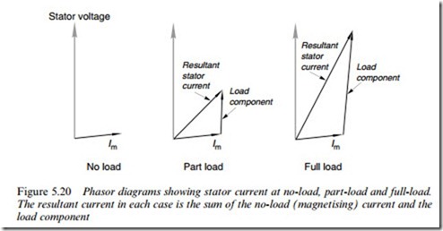
output) power (as distinct from the original magnetising current which was seen to be reactive), this additional ‘work’ component of current is more or less in phase with the supply voltage, as shown in the phasor diagrams (Figure 5.20).
The resultant stator current is the sum of the magnetising current, which is present all the time, and the load component, which increases with the slip. We can see that as the load increases, the resultant stator current also increases, and moves more nearly into phase with the voltage. But because the magnetising current is appreciable, the diVer- ence in magnitude between no-load and full-load currents may not be all that great. (This is in sharp contrast to the d.c. motor, where the no-load current in the armature is very small in comparison with the full- load current. Note, however, that in the d.c. motor, the excitation (Xux) is provided by a separate Weld circuit, whereas in the induction motor the stator winding furnishes both the excitation and the work currents. If we consider the behaviour of the work components of current only, both types of machine look very similar.)
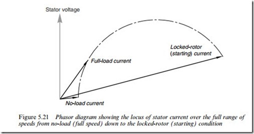
The simple ideas behind Figure 5.20 are based on an approximation, so we cannot push them too far: they are fairly close to the truth for the normal operating region, but breakdown at higher slips, where the rotor and stator leakage reactances become signiWcant. A typical current locus over the whole range of slips for a cage motor is shown in Figure 5.21. We note that the power factor becomes worse again at high slips, and also that the current at standstill (i.e. the ‘starting’ current) is perhaps Wve times the full-load value.
Very high starting currents are one of the worst features of the cage induction motor. They not only cause unwelcome volt drops in the
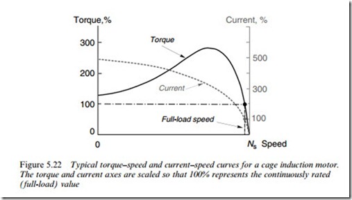
supply system, but also call for heavier switchgear than would be needed to cope with full-load conditions. Unfortunately, for reasons discussed earlier, the high starting currents are not accompanied by high starting torques, as we can see from Figure 5.22, which shows current and torque as functions of slip for a general-purpose cage motor.
We note that the torque per ampere of current drawn from the mains is typically very low at start up, and only reaches a respectable value in the normal operating region, i.e. when the slip is small. This matter is explored further in Chapter 6, and also by means of the equivalent circuit in Chapter 7.


