ACOUSTICS
Usually little attention is paid to the part that the listening room plays in the general problem of obtaining hi-fi. If we can gain a basic understanding of what it takes to make a good listening room, then there is much we can do to ensure that the money invested in hi-fi equipment doesn’t go down the drain. Much knowledge has been accumulated regarding the acoustic problems of concert halls which can, in turn, be applied to our own listening areas.
REFLECTION OF SOUND
A free sound wave travelling through air strikes a uniform, large, solid, plane surface and gets reflected in the same manner as a light ray. The following facts in connection with reflection of sound are to be noted:
1. The analysis of reflection from curved surfaces may be derived by applying the laws of reflection of light.
2. A concave surface leads to the concentration of reflected waves at certain points. Hence concave surfaces maybe provided to work as reflectors.
3. A convex surface tends to spread the reflected waves. Hence, convex surfaces may be used with advantage to spread the sound throughout the room.
4. The study of laws of reflection of sound helps in selecting the proper shape of the room with regard to distribution of sound in that room.
5. The assumption that sound is reflected in the same manner as light is true only for limited circumstances and hence great caution should be exercised while applying the laws of reflection of sound.
REVERBERATION
A sound, once started in a room, will persist by repeated reflections from the walls until its intensity is reduced to the point where it is no longer audible. If the walls are good reflectors of sound waves—for example, hard plaster or marble— the sound may continue to be audible for an appreciable time even after the original sound stops. The repeated reflection that results in this persistenceof sound is called reverberation.
In an auditorium or classroom, excessive reverberation may be highly undersirable. For a given speech, sound or musical tone will continue to be heard by reverberation while the next sound is being sent forth. The practical remedy is to cover the walls with some sound absorbent material, usually a porous substance like felt compressed fibre board, rough plaster or draperies. The regular motions of air molecules, which constitute the sound waves, are converted into irregular motions (heat) in the pores of such materials, and consequently less sound energy is reflected.
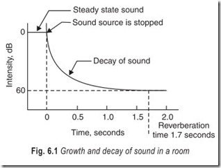
Suppose that a sound whose intensity is one million (106) times that of the faintest audible sound (threshold of hearing) is produced in a given room. The time this sound takes to die away to inaudibility is called the reverberation time.
For an average speaker the ratio  so that m = 60 dB. The time for reverberation is thus defined as the time required by the reverberant sound to decay one – millionth of its initial value. This naturally corresponds to a drop of 60 dB. This is shown in Fig. 6.1.Some reverberation is desirable, especially in concert halls; otherwise the room will sound too dead. For a moderate sized auditorium the reverberation time should be of the order of 1 to 2 s. For a workroom or factory, it should be kept to much smaller values, as sound deadening in such cases results in greater efficiency on the part of workers with much less attendant nervous strain.
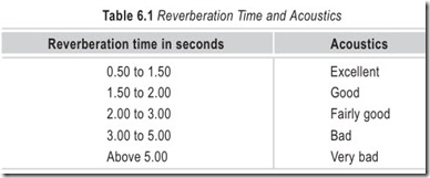
The selection of the correct time of reverberation is called the optimum reverberation time and it will depend on the acoustics of the room. Table 6.1 gives the relation between reverberation time and acoustics of the room. If the reverberation time is too long it results in overlapping of speech, if it is too short, it produces the effect of deadness.
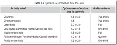
Table 6.2 gives the recommended values of optimum reverberation time for halls designed for various purposes after considering the indicated audience strength.
ABSORPTION OF SOUND
When a sound wave strikes a surface, part of its energy is absorbed by friction, part of its energy is transmitted and the remaining part of its energy is reflected. As reverberation directly depends on the loss of energy of sound waves due to friction, it is of great importance. This property of a surface by which sound energy is converted to some other form of energy is known as absorption and the absorption coefficient of a surface indicates the degree to which this surface affects the absorption of sound. It is thus the ratio of the energy obsorbed by the area to the energy striking the area.
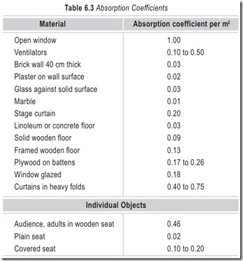
The value of the coefficient of absorption will depend on the frequency of the sound. Table 6.3 gives the value of coefficient of absorption for some of the common surfaces. These values correspond to the normal
frequency of 500 Hz. It may be noted that the coefficient of obsorption for an open window is taken as unity. This is very easy to understand as sound waves approaching an open window must completely pass through it.
SABIN’S EQUATION
Prof W.C. Sabin of Harvard University, U.S.A., carried out a number of experiments in rooms of different sizes and was able to establish the following formula which is known as Sabin’s equation.
where t = reverberation time in seconds
V = volume in m3
and a = total absorbing power in m2 – Sabins
= (a1S1 + a2S2 + a3S3 + …….) absorption units of individual objects .
S1, S2, S3, etc; being coefficients of absorption of respective surfaces a1, a2, a3 etc;
The unit of sound absorption is m2 – Sabin and it is equal to sound absorption of one square metre area of a fully open window. Since V and a can be worked out as per plans and specifications of the structure, it is possible to design a structure for any desired value of reverberation time.
LISTENING ROOM CHARACTERISTICS
A room can be compared to a loudspeaker enclosure. Both the room and the enclosure are surrounded by six surfaces. The differences between the two lie in their size and composition. Yet the similarity in construction is great enough to warrant a comparison.
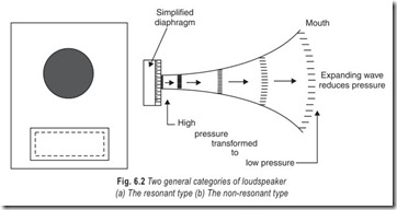
Loudspeakers fall into two general categories. First the resonant enclosure, Fig. 6.2 (a), such as the bass- reflex type, with the characteristic resonance determined by the enclosure’s size and the port in the baffle. Then there is the non-resonant type, Fig. 6.2 (b) which employs the largest possible horn mouth to minimise any possible resonant condition.
Similarly, rooms may be thought of as resonant or non-resonant, with the degree of resonance or non- resonance dependent upon their shape, size and the materials contained in them.
Unlike the speakers with a single major resonance, rooms and enclosures may, in general, have several resonances or modes of vibration. Rooms are rectangular in shape and may have many natural resonances, depending on the room’s length and other dimensions. These other dimensions can also develop their own resonance modes. Thus we can expect that our listening room will have several natural resonances that are completely a function of its size and relative dimensions and partly a function of its liveness.
LIVE ROOMS
Live rooms are those with a great deal of resonance. The best example of a live room is a tile-lined bathroom.
The hard smooth surfaces of the tiles reflect sound almost as well as mirrors reflect light. The constant and repeated reflection of sound from one hard wall to the other, with little absorption, builds up the sound around the ear. This quality of room liveness is a function of the room’s normal mode of vibration. Such a room may be detrimental to smooth audio reproduction.
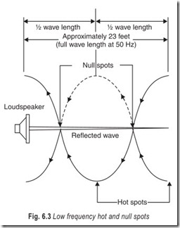
The reflection of sound from one wall to the other and the room’s normal mode of vibration set up hot spots and null spots of sound energy for different frequencies and for different areas of the room. Rooms vibrate and respond most readily to low frequencies. Thus, as shown in Fig. 6.3, a standing wave may be produced for a particular frequency, resulting in peaks at some points and complete cancellation at others. This condition often causes disagreement as to what two people hear in the same room. For instance, if one were at a spot where there was reinforcement due to the standing wave, he might hear mostly bass notes. If some other person were standing at a point of cancellation, he would hear far less bass notes.
To carry out a truly objective listening test, a hi-fi system must be heard from many different positions in the room. Your location in the listening room is of considerable importance. The loudspeaker’s position in the room will also affect the final results. A live room may produce many response irregularities that materially affect the system’s smoothness.
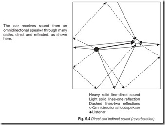
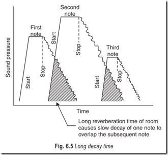
A live room, especially one in which there are excessive wall reflections (Fig. 6.4), has a long reverberation time. In the highly reverberant room, the reproduction seems louder than normal for an amplifier with
moderate audio power. Since a high reverberation time means that the sound is not being absorbed, this makes the sound louder to the ear (Fig. 6.5).
Another characteristic of live rooms is that the directivity characteristic of the reproducing unit is considerably changed by the room’s reflective properties. With highly reverberant walls, successive reflections greatly diffuse the several radiating beams from the loudspeaker. This effectively increases the uniformity of reproduction of the higher frequencies throughout the room.
In a too-live room, then, we may say that the articulation will deteriorate, that irregularities of low-frequency response will occur, that the system will sound louder, and that the sound will be more diffused.
DEAD ROOMS
The dead room is characterised by the high degree of sound it absorbs. If the walls were totally absorbing, all the sound would be lost since no waves would be reflected. Thus a totally absorbent room would not only attenuate the wall-to-wall reflections but would also reduce the room’s normal mode of resonance. An over- damped (dead) room wastes any acoustic power produced in it.
In a dead room, the system’s high-frequency distribution depends solely on the loudspeaker and baffle combination. If the speaker’s high-frequency beam is sharp, the listener’s position in the room will determine how many highs and how much of them will be heard. For the low frequencies, the dead room exhibits fairly uniform distribution characteristics with no standing waves. Therefore, few low-frequency peaks or null points appear throughout the room.
Room size is closely related to the amount of reverberation desired. Generally, small rooms should have less reverberation time than large rooms. If we are in a small room, we are closer to both the loudspeaker and the sound-reflecting surfaces. Reflections will therefore reach us sooner than those from the walls of a larger room. Consequently, if we want a clear separation between notes, the time for the reflected sound to reach us in the small room must be reduced.
ABSORBENT MATERIALS
Various types of absorbent materials are available in the market under different trade names. The value of coefficient of absorption is supplied by the manufacturer. Following are some of the most common types of absorbent materials.
1. Hair felt : This material was used by Prof. Sabin in his experimental works. The average value of coefficient of absorption of 25 mm thick hair felt is 0.60.
2. Acoustic plaster : Also known as fibrous plaster, it includes granulated insulation material mixed with cement. If the quantity of cement is more than that required, the plaster will not have sufficient pores to become effective for acoustics. If the quantity of cement is less than that required then plaster will not have enough strength. Thus, the quantity of cement should be carefully decided. For a thickness of 20 mm and density of 0.10 g/cm3, the acoustic plaster possesses an absorbent coefficient of 0.30 at 500 Hz. Acoustic plaster boards are also available. They can be fixed on the wall and their coefficient of absorption varies from 0.15 to 0.30.
3. Acoustic tiles : These are made in the factory and sold under different trade names. The absorption of sound is uniform from tile to tile and they can be fixed easily. However, acoustical tiles are costlier than other absorbent materials. They are most suitable for rooms in which only a small area is available for acoustical treatment.
4. Strawboard : This material can also be used as absorbent material. With a thickness of 13 mm and density of 0.24 g/cm3, it possesses a coefficient of absorption of 0.30 at 500 Hz.
5. Pulp boards : These are soft boards which are prepared from compressed pulp. They are cheap and can be fixed by ordinary panelling. The average value of coefficient of absorption is 0.17.
6. Compressed fibre boards : This material may be perforated or unperforated. The average coefficient of absorption of the former is 0.30 and for the latter it is 0.52. It has a density of 0.30 g/cm3.
7. Compressed wood particle board : This material is provided with perforations and it can be painted also. With a thickness of about 13 mm, the average coefficient of absorption is 0.40.
8. Perforated plywood : This material can be used by forming composite panels with mineral wool and cement asbestos, or mineral wool and hardboard. It is generally suspended from trusses. The average value of coefficient of absorption for the former is as high as 0.95 and for the latter it is about 0.20.
9. Wood wool board : This material is generally used with a thickness of 25 mm and has density of 0.40 g/cm3. The average value of coefficient of absorption is 0.20.
10. Quilts and mats : These are prepared from mineral wool or glass wool and are fixed in the form of acoustic blankets. The coefficients of absorption of such quilts and mats depend on the thickness, density, perforations, mode of fixing, nature of backing and frequency of sound.
ACOUSTIC DESIGN OF AUDITORIUMS
The following conditions should prevail in an auditorium possessing good acoustical properties.
1. The initial sound should be of good intensity or loudness.
2. The sound which is produced should be evenly spread over the whole area covered by the audience.
3. The initial sound should be clear and distinct.
4. The initial sound should reach the audience with the same frequency and intensity.
5. All undesired sound should be reduced to such an extent that it will not interfere with the normal hearing of speech and music.
The following factors play an important role in the acoustic design of an auditorium.
(i) Volume : The best guide for deciding the volume of a proposed auditorium will be the detailed study of an existing auditorium used for similar purposes. However, it is found from various
considerations that the volume of auditorium per seat should be very near to 4.2 m3 and it should not usually exceed 5.7 m3 per seat.
(ii) Shape : It involves geometrical aspects of the hall. The paths followed by reflected sounds are traced and concentration of sound waves, if any, are noted. Concave walls are not good for acoustic purposes as they tend to concentrate sound waves. Plain walls are better. But convex walls are excellent and are used to reduce the possibilities of echoes to the minimum possible extent.
(iii) Sound absorption : Adequate absorbing surface should be provided in the hall to control the reverberation. The acoustical design of an auditorium will be incomplete without the provision of such a surface. Careful study of the hall should be made before recommending the type of absorbent material and its location in the hall.
ACOUSTICS OF STUDIOS
The term studio means a room where sound is picked up by a microphone and it includes radio-broadcasting station, television station and sound-recording studio. The acoustic design of a studio requires the following special precautions to be taken for its efficient working.
1. The noise level in the studio should be brought down to 20 to 30 dB.
2. Echoes should be completely eliminated.
3. The finish on the outside surfaces should be of a sound reflecting material.
4. Partition walls and exterior walls of the studio should be sufficiently rigid to resist vibration and to prevent resonance.
5. The finish on the interior surfaces of walls, ceilings and floors should be of absorbent materials.
This will help in reducing time of reverberation.
6. Provision of windows in the studio should be minimum so as to prevent transfer of external noise into the studio.
7. Suitable sound insulation should be provided to air-conditioning machinery and such other equipments, so that equipment vibration is not carried upto the working chambers of the studio.
8. In a multi-studio building, it is preferable to locate all the studios on the same floor. In no case studios should be located one above the other. There should be a minimum space of one floor between two consecutive studios in elevation.
9. Heavy curtains and draperies may be used with advantage to control the time of reverberation in the studio.
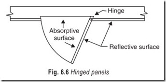
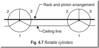
10. In order to control optimum reverberation time (acoustical conditions) of the studio, arrangement of hinged panels (Fig. 6.6) in walls or rotable cylinders (Fig. 6.7) should be made.
In the case of a hinged panel arrangement, a hinge is provided and one surface of the hinged panel is absorptive while the other is reflective. Hinged panel construction is cheap and easy to maintain. In place of hinged panels, revolving panels with a hinge at the centre may also be provided and two different absorbing materials may be provided on both faces of the revolving panel. In case of rotable cylinders, drums of required diameter are suspended from the ceiling. The three surfaces of the drum, each subtending an angle of 120° at the centre, are provided with different absorptive materials. The cylinders can be rotated by rack and pinion arrangement and thus a desired combination of two surfaces can be exposed to the room.
SOUND INSULATION
Sound insulation or sound proofing is used to indicate the reduction in the level of sound when it passes through a building component. Sound insulation and sound absorption are quite different terms. The purpose of a sound-insulated construction is to prevent the sound from passing through it. Hard materials in general are poor sound absorbers but they are good sound insulators.
The purpose of a sound absorbent material is to reduce the sound reflected from a surface. Hence,porous materials in general are good sound absorbers, but they are poor sound insulators.
Insulation of sound is measured in an adjoining room while absorption of sound is measured in the same room.
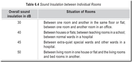
Table 6.4 shows the desirable levels of sound between individual rooms for air-borne sound.
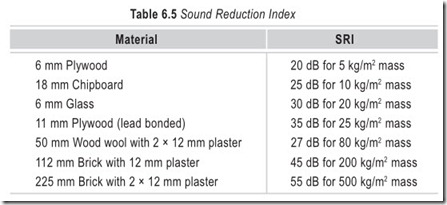
When an airborne sound passes through any structure, loss of sound intensity takes place. This is expressed in terms of sound reduction index (SRI) or transmission loss (TL). Sound reduction index of some materials is given in Table 6.5.
NOISE
There are two distinct types of noise; indoor noise and outdoor noise.
Indoor noises are created in the adjacent room or in the same room where noise is noticed. The sources of indoor noises are moving of people, crying of babies, playing of radios, banging of doors, traffic in staircase, movement of furniture, conversation of the occupants, operation of cisterns and water closets, noise of typewriters, working of machines nearby, etc.
Outdoor noises are created from nearby streets and the largest source of outdoor noise is generally the automobile traffic on the road. The other sources of outdoor noises are railways, aeroplanes, loudspeakers, and machines in nearby factories etc.
Noise is transmitted to the room through walls, ceilings or conduits. The origin of transmitted noise may be air borne or due to impact.
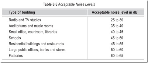
The maximum level of noise which neither annoys the occupants nor damages the acoustics of the building is termed as acceptable noise level in the building. It depends on (a) nature of the noise (b) type and use of the building (c) time of fluctuation of the noise (d) background noise
Table 6.6 gives the generally acceptable noise levels for different structures from the point of view of economy, comfort, and practical considerations of the conditions prevailing in our country.
EXERCISES
Descriptive Questions
1. Discuss the significance of reverberation.
2. What will happen if the reverberation time is
(a) too long (b) too short
3. Explain the difference between an acoustically dead room and an acoustically live room.
4. Define
(i) Sabin (ii) Absorption coefficient
(iii) Optimum reverberation time (iv) Sound reduction index
5. What are the characteristics of a listening room?
6. Differentiate between a sound absorber and a sound insulator.
7. What are the factors that you will consider while designing an auditorium?
8. Give three examples each of use of sound absorbers and sound insulators.
9. What are the types of noise encountered in architectural acoustics?
Multiple Choice Questions
1. Concave surfaces may be provided to act as
(a) absorbers (b) reflectors
(c) insulators (d) none of the above
2. Convex surfaces may be used to
(a) absorb the sound (b) spread the sound
(c) concentrate the sound (d) none of the above
3. The coefficient of absorption of an open window is taken as
(a) 1 (b) 2
4. Rooms and enclosures may have
(a) a single resonance (b) several resonances
(c) two resonances (d) none of the above
5. Rooms vibrate and respond most readily to
(a) low frequencies (b) high frequencies
(c) mid frequencies (d) none of the above
6. To make a truly objective listening test, a hi-fi system should be heard from
(a) a single listening position (b) different listening positions
(c) the centre of the listening room (d) a corner of the listening room
Fill in the Blanks
1………………………………………. of sound is called reverberation.
2. Too long a reverberation time results in………………………………………. of sound.
3. Too short a reverberation time produces the effect of ………………………………………..
4. The ratio of the energy absorbed by the area to the energy striking the area is called………………………………………..
5. The coefficient of absorption depends on the………………………………………. of sound.
6. The unit of sound absorption is………………………………………..
7. Liveness of room may be……………………………………….to smooth audio reproduction.
8. A live room may produce many response………………………………………..
9. In a live room articulation will ………………………………………..
10. Small rooms should have………………………………………. reverberation time than large rooms.
11. The noise level in a studio should be brought down to ………………………………………..
12. Heavy curtains and draperies may be used to control the ………………………………………..
13. Porous materials are good sound………………………………………..
14. Hard materials are good sound………………………………………..
15. Insulation of sound is measured in an………………………………………..
16. Absorption of sound is measured in the ………………………………………..
ANSWERS
Multiple Choice Questions
1. (b) 2. (b) 3. (a) 4. (b) 5. (a) 6. (b)
Fill in the Blanks1. persistence |
2. overlaping of speech |
3. deadness |
|
4. absorption coefficient 7. detrimental 10. less |
5. frequency 8. irregularities 11. 20 to 30 dB |
6. m2- Sabin 9. deteriorate 12. time of reverbertaion |
|
13. absorbers 16. same room |
14. insulators |
15. adjoining room |

