LOCATING CRITICAL TV COMPONENTS
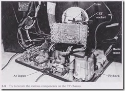
When the front of a TV screen indicates that the trouble might be in the vertical section, such as an improper sweep, locate the vertical section on the TV chassis (Fig. 2-8). Today, most TV chassis use an IC output component on a heat sink for the vertical output circuits. The TV chassis can be broken up into the horizontal, vertical, tuner, intermediate frequency (IF) and video, audio, and CRT sections and high- and low voltage power supplies. Remember that within a TV chassis, sometimes the horizontal section must operate before any voltages are fed to the secondary windings of the flyback to the other circuits.
LOCATING CRITICAL COMPONENTS ON A CASSETTE PLAYER
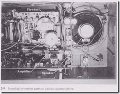
Take a quick peek at the cassette player, and go directly to the components that the symptom may suggest. The cassette motor and tape head are easily identified (Fig. 2-9). The preamp stage follows the tape head, and the audio output circuits are tied to the permanent magnet (PM) speaker.
If the tape player is running slowly, go directly to the cassette motor, belt, and revolving pulleys. A good cleanup can solve most speed problems. when the audio is dead in the right channel, locate the audio output IC on a heat sink, and 1nake critical voltage and semiconductor tests.
LOCATING TV/VCR COMPONENTS
When both the TV and VCR are dead with no tape movement , go directly to the fuse block or low-voltage power supply. Determine if both units work from one power supply. Sometimes a separate power supply is found for the VCR circuits and another de supply for the TV chassis. Then take critical voltage measurements.
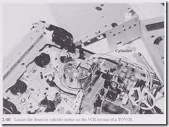
When the cylinder motor runs and then shuts down, suspect a bad cylinder motor or a cylinder motor drive IC. Take critical voltage measurements on the cylinder or drum motor terminals with no motor rotation (Fig. 2-10).
LOCATING CD COMPONENTS
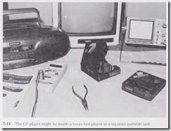
Look over the CD chassis and try to locate the various CD parts. Go directly to the largest electrolytic capacitor when excessive hum is heard in the speakers with the volume turned down (Fig. 2-11). Often the main filter capacitor is from 2200 to 4300 F capacity and is the largest part on the chassis. Clean up the lens asse1nbly when the CD player starts skipping. Start at the digital-to-analog (D/A) IC output when one channel of audio is weak or intermittent. Take critical voltage measurements on the suspected transistor or IC component.
Out of bounds
Check outside the chassis for defective components. If the TV screen is all red when the color control is turned way up, check for defective components on the CRT board on the neck of the picture tube. Don’t overlook defective components that are not on the main chassis. Look for defective transformers, power transistors, voltage regulators, ICs, capacitors, and separate metal heat sinks or chassis. Check for problems in circuits on separate PC boards that are soldered to the rnain PC board. Suspect poorly soldered connections from the horizontal PC board to the main chassis.
Lightning damage in a TV chassis
Sometimes lightning or storm damage may only blow the main fuse. When a TV is hit directly on the power line, you will find many parts damaged. A power outage also can cause damage to many components on a TV chassis. If the house fuse box is blown out of the cabinet with several light bulbs busted and the refrigerator will not run, suspect extreme damage to the TV and sound equipment.
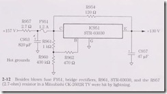
Carefully inspect the antenna terminals and isolation capacitors on the tuner assembly of a TV. Notice if black and burned marks are found at the ac interlock and if several components are damaged in the power supply (Fig. 2-12). Peek at the PC board and notice any burned spots. Also look to see if any PC traces are blown or pulled up from the board. Remember that the low-voltage power supply must operate before any sections function. After all repairs are completed, let the chassis operate for several days before returning it to everyday service.
Burned and damaged
Burned or damaged parts are seen easily on a PC board. However, you might have to blow off dust to see the burned components. Sometimes you can smell burned or charred parts. The PC board might have to be repaired if it has been burned and damaged.
Large parts such as transformers, electrolytic capacitors, and power output transistors can be seen easily. Check for a part number on the body. It is difficult to deter mine the total resistance in charred resistors. If the color code cannot be seen, try to locate a schematic similar to the chassis on the bench.
In many cases the resistance may be close in value for several different known chassis in the same circuit. For instance, two charred boost-dropping voltage resistors were found in a Sony portable TV chassis. Because the correct schematic was not avail able, another Sony portable (KV-1747R) circuit was used that was quite similar. There was no doubt that R720 and R715 were damaged when the picture tube arced over with excessive high voltage. Make sure that the circuits are similar and have the correct operating voltage.
Ac input hot grounds
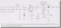
Today, the ac circuits have hot grounds above the common ground in TV chassis’. Notice that the ac input degaussing circuit, silicon diodes, and main filter capacitor are in the hot ground circuits. When taking ac or de voltage measurements in these circuits, make sure that the black voltage probe is on the hot ground side of the filter capacitor. To determine if the low-voltage circuits are functioning, take a de voltage measurement across the main filter capacitor (Fig. 2-13). Do not take the voltage from the common chassis ground because it will not be correct.
TV SMPS hot grounds
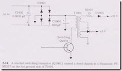
Within the Switching power supply or switch-mode power supply (SMPS), all components on the primary side are connected to the hot ground. Simply locate the switching transformer as the biggest part on the chassis. Take all critical voltage measurements on the Switching regulator IC, transformer, and transistors on the hot ground (Fig. 2-14). Some schematics have a diamond-shaped or triangular symbol indicating the hot ground terminals. The secondary circuits of the switching transformer are connected to the common ground.
The common ground is where most voltages and critical measurements are connected to the common ground terminal of the DMM or scope. Common ground is a reference ground connection. The metal chassis of a TV or amplifier is the common ground. The main reason for using a common grow1d is to simplify the different circuits. The common ground is used as a return path for many different circuits. Most voltages and scope waveforms are taken with the test instrument black probe or gro1md clip connected to the common ground.
Running warm
A red hot or overly warm audio output transistor might show signs on the body from overheating with a cracked or burned bias resistor. Smoking resistors indicate a leaky transistor, IC, or capacitor. Power transformers running red hot might be caused by leaky silicon diodes or electrolytic capacitors. Red hot power output transistors and IC components might be leaky with burned bias resistors. Replace overheated IC components that have a chipped area or white and brown spots on the body.
Check the PC board where overheated parts are tied into the PC board wiring. Often, brown spots on the top, around heated terminals, indicate a poorly soldered joint.
Clean the area and resolder . If the terminal lead will not take solder, cut off the bad terminal end, insert the lead through the PC board hole, and solder.
Red hot-do not touch
The power output IC within a deluxe receiver might indicate overheating with gray streaks on the body and a change in color. Check for burned bias resistors that might be operating quite warm.
A dead high-powered amplifier with a loud hum can be caused by a red hot output transistor. Red hot output transistors in a car radio may have burned open the fuse and charred the hot wire to the receiver. When the horizontal output transistor in a TV chassis runs red hot, suspect insufficient drive voltage or a leaky output transistor. Suspect too-hot-to-touch transistors that are leaky or have
improper bias voltage.
Check the transistor in the circuit for a leaky condition. You may find one transistor leaky and the other push-pull transistor open. Remove both transistors, and test them out of the circuit. Always replace both transistors when one is found to be leaky or shorted. Inspect the bias resistors for burned or charred areas. Check each bias resistor and diode while the transistors are out of the circuit.
Red hot audio output ICs indicate a lealcy’ IC or excessive supply voltage. Most output ICs and transistors will run warm but not red hot. Check for a change in bias resistors and high-power supply voltage. Often, when a red hot IC or transistor is found, the bias resistors are burned or changed in value. Check for leaky directly driven transistors when the output transistor or IC rims red hot.
Same circuits, another chassis
Often the circuits within a TV, cassette, or CD player are the same as the ones you are working on. If you have a new TV chassis that has quit and you have no schematic, compare it with another chassis. Sometimes, even with a schematic, certain voltages are not listed, and with another chassis you can compare voltage and resistance readings. Of course, the chassis must be the same make and have the same chassis setup. Comparison tests can solve a difficult problem when a schematic is not handy.
Often the circuits within TVs, stereos, and radios are the same for several years. If you have a schematic for an older unit, use it. You also can compare the chassis with that of another brand.
If the defective chassis has marked part numbers, use a schematic that is similar.
Take voltage measurements of a transistor from each terminal to common ground.
With an NPN transistor, the positive lead will go to each terminal with the negative probe grounded. Just reverse the test leads for voltage measurements of a PNP transistor. The positive probe is at ground potential with a PNP transistor. Use a DMM for accurate low-voltage tests.
Most voltage tests on a suspected IC should be made with the positive lead at the IC terminals and the negative probe clipped to ground. Write down the voltage measurements on each terminal pin. Then determine if these voltages are correct. Always check the voltage supply pin first. If the voltage is very low, suspect a leaky IC (Fig. 2-15).
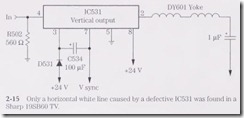
Remove the voltage supply terminal from the PC board wiring to see if the voltage increases. Simply unsolder the pin with solder wick and a hot iron. Flick the pin to make sure that it is loose and not touching the PC board wiring. Now take another voltage measurement.
If the voltage has increased to normal or higher, replace the leaky IC.
