Generators
In very general terms, a motor and a generator may be said to be oppo sites; that is, a motor is a machine that when supplied with electric cur rent can be used for mechanical work, such as driving an industrial machine and the like. A generator, on the other hand, is a machine that is driven by mechanical means to produce electric current. 1\iost generators are rated in kilowatts (kW) and range in size from a fraction of a kilowatt to several thousand kilowatts. A typical generator is shown in Fig. 11-1. This type is portable and is suitable for supplying 120/240 ac up to 3 kW.
DIRECT-CURRENT GENERATORS
Direct-current generators are very similar to de motors in both appear ance and construction. Both have the same types of armature and field poles and are generally identical. For this reason, a de motor can easily be converted into a generator or vice versa.
If a piece of wire is moved through magnetic lines of force, as shown in Fig. 11-2, so the wire cuts across the path of the flux, a voltage will be induced in the wire. Faraday first made this discovery in about 1831. If we then connect a sensitive meter to this wire- thus completing the cir cuit-the needle will indicate a flow of current every time the wire is moved across the lines of force. This induction, of course, generates volt age in the wire, without producing any current, if the circuit is open. In fact, current is never generated; rather, pressure is set up which causes current flow if the circuit is completed. So current always results from the production of pressure first and only when the circuit is closed.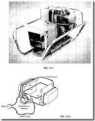
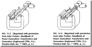
A simple generator is shown in Fig. 11-3 which is a single-turn coil arranged to be revolved in the field of permanent magnets. The ends of the coils are attached to metal slip rings which are fastened to the shaft and revolving with it. This arrangement gives a connection from the mov ing coils to the circuit load by means of metal or carbon brushes rubbing on the slip rings.
Assume that the coil in Fig. 11-3 revolves to the right, or clockwise.
Wire AB will be moving upward through the flux, and the induced pres sure will be in the direction indicated by the arrow on it. At the same time, wire CD is moving downward, and its induced pressure will be in the reverse direction but will join with and add to that of wire AB, as they are connected in series in the loop. Note that the current flows to the nearest collector ring and out along the lower wire to the load, returning on the upper wire to the farthest collector ring and the coil.
Figure 11-4 shows the same coil in Fig. 11-3 after it has turned one half revolution farther, and now wire AB is moving downward instead of up as before. Therefore, its pressure and current are reversed. Wire CD is now in the position where AB was before, and its pressure is also re versed. This time the current flows out to the farthest collector ring and over the top wire to the load, returning on the lower wire.
The discussion thus far has been that of an alternator. If direct cur rent is desired, a commutator must be used, or else some other type of rotary switch, to reverse the coil leads to the brushes as the coil moves around. All common generators produce alternating current in their windings, so we must convert it in this manner if direct current is desired in the external circuit.
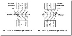
In Fig. 11-5, another revolving loop is shown. Note that wire AB is moving upward, that its current is flowing away from the front of the coil, and that the current of wire CD is flowing in the opposite direction. The coil ends are connected to two bars or segments of a simple commu tator, each wire to its own separate bar. With the coil in this position, the current flows out at the right-hand brush, through the load to the left, and reenters the coil at the left brush.
In Fig. 11-6, the coil has moved one-half turn to the right, and wire AB is now moving down, and its current is reversed. However, the com mutator bar to which it is connected has also moved around with the wire, so the current still flows in the same direction in the external cir cuit, producing direct current to the load.
In Fig. 11-6 is shown another illustration of power generation. At A, the lines of force from the field poles are passing downward, and the con ductor is being moved to the right. This will induce a voltage in the wire that will tend to cause current to flow in at the end which is visible. In B in Fig. 11-6, the conductor is moving in the opposite direction, through the same magnetic field; note that the induced voltage has reversed with the direction of the conductor movement.
The circular arrows around the conductors in Fig. 11-6 indicate the direction of the lines of force which will be set up around them by their in duced currents.
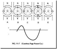
Refer to Fig. 11-7, which shows two conductors of a coil mounted in slots of an armature and revolving clockwise. In their position at A, the conductors are not generating any voltage, as they are in the neutral plane and are not cutting across lines of force. At B, the direction of in duced voltage will be in at conductor F and out at G; if the conductors are connected together at the back of the coil, their voltages will add together.
In position C, the conductors are both in the neutral plane again, so their induced voltage once more falls to zero.
At position D, conductor G is passing the north pole and conductor F is passing the south pole, so they are both moving through the field flux in opposite directions to what they were at position B, and therefore their induced voltage will be reversed. AtE, both conductors are again back in the neutral plane, or at the same point they started from.
A curve indicating the voltage generated is shown below these vari ous steps of generation in Fig. 11-7. At A, the voltage curve is starting at the zero line, as the conductors start to enter the field flux. At B, where the conductors are cutting through the dense field directly under the poles, the curve shows maximum positive voltage. From this point, it falls off gradually as the conductors pass out of the flux at the poles until it again reaches zero at C. Then as the conductors each start to cut flux in the opposite direction, the curve shows negative voltage in the opposite direction or below the line, reaching maximum value at D. AtE, the nega tive voltage has again fallen to zero.
CYCLES AND ALTERNATIONS
When one complete revolution is completed in the simple two-pole gen erator, it also completes what is called one cycle of generated voltage. Referring again to Fig. 11-7, note the single positive impulse produced by the conductor passing one complete pole, as indicated by the curve from A to C. This is called one alternation, two of which are required to make one cycle. Therefore, each time a conductor passes one north pole and one south pole, it produces one cycle.
There are 360° in a circle, or, for that matter, in one revolution of a conductor on an armature. When referring to generators, the term is usually changed and expressed in electrical degrees. Therefore, the conductor travels 360 electrical deg each time it passes two alternate field poles and completes one cycle. From this it is easily seen that one cycle consists of 360 electrical deg and one alternation consists of 180 electrical deg.
In generators with more than two poles, it is not necessary for the conductor to make a complete revolution to complete a cycle, since one cycle is produced for each pair of poles passed. So a four-pole generator, for example, would produce two cycles per revolution; an eight-pole gen erator, four cycles per revolution, and so forth.
FREQUENCY
Alternating-current circuits have their frequency expressed in cycles per second, the most common being 60 cps, or 60 Hz. Since frequency is ex pressed in cycles per second and a conductor must pass one pair of poles to produce a cycle, the frequency of an ac generator depends on the number of its poles and the speed of rotation.
For example, a four-pole generator rotated at 1800 rpm would pro duce a frequency of 60 cps since its conductors will pass two pairs of poles per revolution, or 1800 X 2 = 3600 pairs of poles per minute. Then, as there are 60 s in a minute, 3600/60 = 60 cps.
A generator with, say, 12 poles would only need to rotate at 600 rpm to produce 60 cps. The conductor in such a generator would pass six pairs of poles per revolution or at 600 rpm would pass 6 X 600 = 3600 pairs of poles per minute, and 3600/60 = 60 cps.
ALTERNATORS
Alternating-current generators are commonly called alternators, most of which are of the revolving field type; that is, the armature conductors are stationary while the field revolves-just the opposite of the generators discussed previously. This type of construction has two very important advantages for large power plant alternators. The first is if the armature conductors are stationary, the line wires can be permanently connected to them, and it is not necessary to take the generated current out through brushes or sliding contacts. This is quite an advantage with the heavy currents and high voltages produced by modern alternators.
Of course, it is necessary to supply the current to the revolving field with slip rings and brushes, but this field energy is many times smaller in amperes and lower in volts than the main armature current.
The other big advantage is that the armature conductors are much larger and heavier than those of the field coils and much more difficult to insulate because of their very high voltage. It is, therefore, much easier to build the armature conductors into a stationary element than it is in a rotating one.
The field, being the lighter and smaller element, is also easier to rotate, and this reduces bearing friction and troubles as well as air fric tion at high speeds.
With large revolving field alternators, the stationary armature is commonly called the stator, and the rotating field is called the rotor.
SINGLE-PHASE SYSTEMS
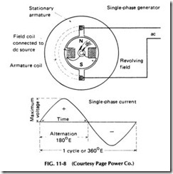
Figure 11-8 shows a simple revolving field alternator with one coil in the slots of the stator, or stationary armature. The circles in the slots show the ends of the coil sides, and the dotted portion is the connection be tween them at the back end of the stator. Inside the stator core is a two pole field core with its coil mounted on a shaft so it can be revolved.
When direct current is supplied to the field core through the slip rings and brushes shown, the core becomes a powerful electromagnet with flux extending from its poles into the stator core. Then, as the field is revolved, the lines of force from its poles revolve with them and cut across the conductors in the stator slots.
As each coil side is passed first by the flux of the north pole and then a south pole, the induced voltage and current will be alternating, as it was with the revolving armature type previously shown. The sine wave be neath the generator shows the complete cycle which will be produced by one revolution of the two-pole field. This particular generator would have to revolve at 3600 rpm to produce 60-cycle energy. Such high-speed gen erators are normally used only for standby power and are never run continuously due to the wear on the parts at the high speed. Revolving fields are made with four or more poles to produce 60-cycle energy at lower speeds.
TWO-PHASE SYSTEMS
Generators and alternators are also made to produce polyphases, such as two-phase and three-phase currents, meaning their currents are divided into more than one part.
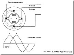
Figure 11-9 shows a simple two-phase alternator, which has two separate coils placed in its stator at right angles to each other, or dis placed 90° from each other. As the field of this generator revolves, it will induce voltage impulses in each of these coils, but these impulses will not come at the same time, due to the position of the coils. Instead, the volt ages will be generated 90 electrical deg apart, as shown in the sine wave in Fig. 11-9.
Referring again to the curve in Fig. 11-9, curve A shows the voltage generated in coil A as the poles pass its sides. As these poles rotate 90 o farther, their flux cuts across coil B and produces the voltage impulses shown by curve B which are all90 o later than those in curve A. These two separate sets of impulses are each carried by their own two-wire circuits as shown in the diagram.
Consequently, a two-phase circuit is simply a circuit of two parts or having two sets of alternations occuring 90 o apart. Note from the curve in Fig. 11-9 that these alternations or impulses overlap each other and that while one is at zero value, the other is at maximum value, always maintaining voltage in one phase or the other as long as the circuit is alive. This feature is quite an advantage where the energy is used for power purposes, as these overlapping impulses produce a stronger and steadier torque than single-phase impulses.
For this same reason, three-phase energy is still more desirable for motor operation and power transmission and is much more generally used than two-phase energy.
THREE-PHASE SYSTEMS
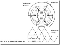
The drawing in Fig. 11-10 shows a simple three-phase alternator, with three coils in its stator spaced 120 electrical deg apart. As the field poles revolve past coils A, B, and C in succession, they induce voltage impulses which are also 120° apart, as shown in the curves in the drawing.
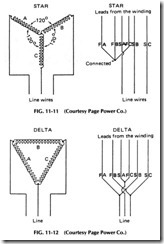
The line leads are taken from the coils at points 120° apart, and the other ends of the coils are connected together at F. This type of connec tion is known as the star or Y connection of the coils to the line. Another common connection for three-phase windings is the delta connection. See Figs. 11-11 and 11-12.
Figure 11-11 shows the method of making a star or Y connection with ac windings, while Fig. 11-12 shows delta connections. By compar ing these two forms of connections, you will note that the delta connec tion has only half as many turns as the Y connection. Since the number of turns or coils in series directly affects the voltage, theY connection will produce higher voltage than the delta, and when used on a motor, theY connection will enable the motor to operate on higher line voltage.
The delta connection, however, has two windings in parallel between any two line or phase leads, so it will have greater line current capacity than the Y or star connection.
Since the star or Y connection places twice as many coils in series be tween the line wires as the delta connection, it might appear to give double the voltage of a delta system. However, the voltage increase will not be double because the spacing of the two windings in the alternator is 120° apart, and consequently their maximum voltages occur at slightly different periods of time. The placing of the C phase winding between the windings of the A and B phases actually reverses its phase relation to the other two windings by 180° and in the star or Y connection this puts phase voltages in series which are only 60° apart. So when two equal volt ages which are 60° apart are connected in series, their total voltage at any instant will not be double but will be approximately 1.73 (the square root of 3) times the voltage of either one.
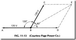
To better understand how the sum of polyphase voltages are de rived, vector diagrams are sometimes used. The one in Fig. 11-13, for ex ample, shows how polyphase values are obtained. In general, the lines are drawn to scale and at the proper angle to represent the voltages to be added. The line from B to A represents 120 V of one winding, and the line from B to C represents 120 V to another winding 120° out of phase with the first. However, as one of the phases is reversed with respect to the other, the line is drawn in the opposite direction from B to C to represent the voltage 180° displaced or in the reverse direction to that shown by line BA. This voltage will then be 60° displaced from that in the other phase, shown by line BC.
By completing the parallelogram of forces as shown by the dotted lines, the vectorial sum of the two-phase winding voltages can now be determined by measuring the diagonal line BE. If the lengths of the lines BC and BD are each allowed to represent 120 V by a scale of Ys in. for each 10 V, the length of line BE measures out to 1.73 times as long as either of the others, so it will represent about 208 V.
The important fact to remember when working with polyphase cir cuits is that the star or Y connection always gives 1.73 (1.732 to be exact) times the voltage of the delta connection. So in changing from delta to star, multiply the delta line voltage by 1.732, and in changing from star to delta, divide the star line voltage by 1.732, or multiply it by .5774, to obtain the delta line voltage.
