Fuel Pump Service
FUEL PUMP TESTS
The fuel pump can be tested on the car with a pressure gauge, a hose and a pint measuring can. With this equipment, it is possible to check the fuel pump to see if it is delivering the proper amount of gasoline at the correct pressure.
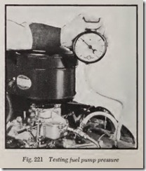
Pressure Test-To make the pressure test, dis connect the fuel pipe at the carburetor inlet and attach the pressure gauge and hose between the carburetor inlet and the disconnected fuel pipe, Fig. 221. Take the pressure reading with the engine running. The pressure should be between 2 and 6 pounds, depending on the pump model and the car on which it is installed. The pressur e should remain constant or return very slowly to zero when the engine is stopped.
Capacity Test-To m ake this test, connect hose so the pump will deliver gasoline into the pint measure held at carbur etor level. Run the engin e at idle speed and note the time it takes to fill the measure. On the avera ge it should t ake from 20 to 30 seconds, depending on the pump being tested.
WHEN PRESSURE IS LOW
Low pressur e indicat es extreme wear on one part, small wear on all parts, ruptured diaphragm, dirty valve or gummy valve seat.
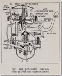
Wear in the pump usually occurs at the rocker arm pivot pin, Figs. 222 and 223, and on the contacting surfaces of the rocker arm and links. Due to the leverage design, wear at these points is multiplied five times in the movement of the diaphragm. It is apparent therefore, that very little_wear will materially reduce the stroke of the diaphragm. The worn parts must be replaeed for a satisfaetory correetion.
The diaphragm pull rod has an oil seal around it whieh prevents the hot oil vapors from the erankease coming in eontact with the diaphragm. If this seal is damaged, the oil vapors have a ten deney to shorten the life of the diaphragm.
The first three eonditions-extreme wear on one part, small wear on all parts, and ruptured dia phragm-are brought about by usage, while dirty and/or poor fuel is usually the cause of valve trouble.
WHEN PRESSURE IS HIGH
High pressure is eaused by a tight diaphragm, fuel between diaphragm layers, diaphragm spring too strong, pump link frozen to rocker arm.
A. tight diaphragm will streteh slightly on the down stroke. As the pump operates, the dia phragm will rebound on the up stroke beyond its normal position, mueh as a stretehed rubber band when it is suddenly released. This rebound will cause a higher than normal pressure in the pump ehamber.
A loose diaphragm retainer nut or poor riveting on the diaphragm assembly may allow fuel to seep between the diaphragm layers. This will cause a bulge in the diaphragm and have the same effect as a diaphragm that is too tight.
A diaphragm spring that is too strong also eauses a high pressure, for the diaphragm will operate longer before pressure of the fuel on the diaphragm will overcome the diaphragm spring.
On a eombination pump, Fig. 223, there are times when the operating parts may beeome badly corroded and the links freeze to the rocker arm. In this eondition the pump operates continually, re sulting in a very high pressure and a flooding carburetor.
The remedy for all these conditions is to remove the pump for replaeement or repair, using a repair kit.
WHEN CAPACITY IS LOW
A pump is extra efficient and will never starve the engine when it supplies fuel equal to or above the eapaeity of the pump. The pressure, of course, must be within speeifications.
Low capaeity is usually caused by an air leak in the intake pipe at these points: fuel pipe fitting at pump, bowl flange or diaphragm flange, fuel bowl. (It is assumed that the conditions of too little fuel have already been cheeked and the fuel pump is the eausc of the difficulty.)
An air leak at fuel pipe fittings indieates either poor installation of pump or a defective fitting. The fitting should be tightened or replaced.
A leak at the diaphragm flange may be caused by a warped cover casting, loose diaphragm cover screws or foreign material between cover casting and diaphragm.
A leak at the bowl flange of the eover casting can usually be corrected by the installation of an extra gasket. A warped top eover indicates that the pump must be replaced.
A chipped glass or bent metal bowl may cause a leak at the bowl flange as may a defective gasket or foreign material between gasket and bowl or cover casting. A chipped glass bowl must be re placed while a dented metal bowl can be straightened.
VACUUM PUMP TROUBLES
To assist the manifold vacuum to operate the windshield wiper at a uniform rate under any engine load is the only function of the vacuum pump, Fig. 223. Of course, “uniform rate” infers a wet windshield glass and not one covered with snow or ice. Failure to do the above indicates difficulty in either the vacuum system of the pump, windshield wiper motor, or tubes and con nections.
Symptoms of trouble in the vacuum section show up in four ways: oil consumption, slow windshield wiper action, poor idle, noise.
In some cases it has been found that an engine which has given very good oil mileage suddenly appears to be using oil. Upon investigation, it will often be found that the vacuum booster has a ruptured diaphragm and is drawing oil fumes from the crankcase into the intake manifold. This can be checked by removing the cover of the vacuum section.
When the windshield wiper slows down exces sively under engine load, it usually is an indica tion of a ruptured vacuum diaphragm or defective valve action in the vacuum pump. This condition may not be discovered immediately as the wind shield wipers may not be used for long intervals.
Oil will be evidenced in the cover casting re cesses if the diaphragm is ruptured. The pump should be removed and the diaphragm replaced.
On some cars the engine will idle very poorly when the vacuum diaphragm is ruptured. This is true when the tube from the vacuum pump is connected to one end of the intake manifold. The air leak through the vacuum section will give those cylinders on the end a lean mixture which results in a miss or poor idle. In many cases, this leads one to believe the valves of the engine are sticking; but if they are ground, the miss or poor idle remains.
This condition can be checked by removing the vacuum pump tube at the manifold and plugging the hole. If the miss or rough idle disappears, the trouble is an air leak through the pump or tube connections. The pump should be removed and repaired or the connections tightened to eliminate this trouble.
VACUUM PUMP TEST
With a combination fuel and vacuum pump the windshield wiper should operate at 80 to 100 strokes per minute through all ranges of car speed and load. The windshield should be wet when the test is made, otherwise the action will be slow.
Checking with Vacuum Gauge
To check the vacuum section, disconnect both inlet and outlet tubes and attach a vacuum gauge to the inlet (side that goes to windshield wiper). It is assumed that the engine, windshield wiper motor and blade, and connecting tubing have been checked and are in satisfactory condition.
Read the vacuum gauge when the engine is running at 1000 rpm (about 20 mph). It should read from 7 to 12 inches of vacuum on a normal pump. If the reading is below this figure, the pump should be removed and repaired or re placed. When making this test, the tube to the manifold should be plugged and the pump outlet should always be open or damage may result to the mechanism.
Checking Without Gauge
Disconnect the outlet tube (to manifold) from the pump and plug the end. Then operate the engine from an idle through slow acceleration to about 40 mph. If the wiper starts operating at abour-15 mph and reaches full speed at about 40 mph, the vacuum section is okay. If it does not operate, it may be the windshield wiper motor. This can be checked by connecting the intake manifold directly to the windshield wiper tube. Then slowly accelerate the engine from idle to about 25 mph. The wiper should operate at full speed. If it does not it can be assumed the wiper motor or tubing is defective.
FUEL PUMP OVERHAUL
Although there have been many types of fuel pumps produced, it is not necessary to know all of the details of every type in order to service them. Therefore, we will describe the procedure for overhauling a popular type fuel pump which pumps gasoline only, and a combination fuel and vacuum pump, which, in addition to pumping fuel, also assists in the operation of the windshield wiper as already mentioned.
For each make and model of pump, a repair kit is available which contains all the parts needed to obtain a thoroughly satisfactory job. The parts include everything except the body and cover castings.
Servicing Fuel Pump
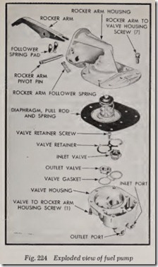
An exploded view of a typical fuel pump is illustrated in Fig. 224. All parts of the pump ex cept the diaphragm should be thoroughly cleaned in a suitable solvent. Gum deposits can be re moved with denatured alcohol. Examine dia phragm for cracks, breaks or torn screw holes. Inspect push rod oil seal for wear, breaks or tears and examine the valves for proper sealing.
To disassemble, remove the pivot pin in order to disengage the rocker arm from the push rod. Remove the body screws and separate the rocker arm housing from the valve housing. Valves are held in position by a spring retainer.
When installing valves, always use a new gasket. Tighten retainer securely. Install the dia phragm into the rocker arm housing. Tie the follower spring down on the arm and install the arm into the housing, engaging the push rod. Install pivot pin and remove the material used to tie down the follower spring.
Assemble the rocker arm housing to the valve housing but do not tighten the screws. Hold the diaphragm in fully compressed position and then tighten the screws. This will prev ent tearing the diaphragm.
Combination Pump Disassemble
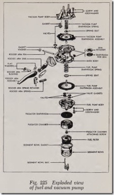
Fig. 225 shows an exploded view of a late model fuel and vacuum pump, which is fairly repr sentative of all types of combination pumps. To disassemble, proceed as follows:
1. Loosen retainer nut on bail to release sedi ment bowl. Remove bowl, gasket, filter, and bail.
2. Scribe a mark with a file on the main body, fuel pump body and pulsator chamber so that these parts may be reass embled in their origi nal position.
3. Remove one screw and lock washer retaining the pulsator chamber to the fuel pump body.
Then remove the pulsator chamber and di aphragm.
4. Remove the screws and washers that hold the fuel pump body to the main body. Remove fuel pump body.
5. Remove staking marks around valves and pryvalves out of fuel pump body with screw driver.
6. Press the diaphragm in and twist to unhook the rod from the rocker arm link. If the rod is not readily removed by this method, it may be unhooked by pushing against it with a blunt punch inserted through the rocker arm opening.
7. Remove one attaching screw on each side of the vacuum pump body and replace each with two long ( 1 “) screws. These screws will serve as pilots and also relieve spring tension.
8. Remove remaining attaching screws and lock washers, then back off alternately on each pilot screw until all spring tension is relieved. Then remove pilot screws and vacuum body.
9. Remove diaphragm return spring and spring seat.
10. Remove vacuum pump diaphragm, using same procedure as when removing fuel pump di aphragm.
11. Remove staking marks around valves. Pryvalves from main body and vacuum body with screwdriver.
12. File or grind peened end of rocker arm pin flush with washer.
13. Drive pin from main body with blunt punch.
14. Remove rocker arm assembly.
15. Remove staking marks and pry vacuum and fuel diaphragm rod seals and retainers from main body.
16. Smooth all seal and valve countcrbores in main body, fuel pump body, and vacuum pump body with scraper. This will remove metal projections.
Combination Pump Assemble
1. After cleaning all parts and obtaining the re pair kit, install the fuel and vacuum dia phragm rod seals and retainers with a suitable driver and stake the body to secure retainers and seals in place.
2. Place gaskets in position and install both fuel pump outlet and inlet valves. Stake valves securely in place.
3. Install new valves and gaskets in main body and vacuum booster pump body. Stake all valves in vacuum pump body. Stake all valves except inlet valve in main body. Inlet valve is located adjacent to pump mounting flange. A very thin coat of sealing compound applied to the edges of the valve cage and rod seal in the vacuum booster section will help prevent oil leakage.
4. Assemble rocker arm.
5. Place rocker arm spring in position and insert arm assembly into main body. Hold in place with a thin punch.
6. Hold pump body so that fuel side is facing down. Jar the body so that diaphragm oper ating link will fall toward the fuel pump side.
7. Insert fuel diaphragm rod, with spring and seat in place, through the main body seal. Hook rod over end of rocker arm link. Lubri cate diaphragm rod lightly with cup grease before installing.
8. Using a new rocker arm pin, drive the holding
punch (mentioned above) out of the pump body. Install pin retaining washer and peen pin.
9. Place fuel pump body in position on main body, aligning the scribe marks made prior to disassembly. Make sure that the diaphragm is in the proper position. Start all screws, mak ing sure they pass through the holes in the di aphragm without tearing the fabric. Tum all screws in evenly.
10. Hold main body so that vacuum side faces down. Jar the body to cause rocker arm dia phragm operating links to fall toward vacuum pump side.
11. Insert vacuum diaphragm rod through the main body seal, tilting rod slightly away from rocker arm links. Hook rod over both link arms. Lubricate rod lightly with cup grease before installing.
12. Place spring seat and diaphragm return spring on diaphragm.
13. Drop vacuum booster pump body over the spring, and align the scribe marks made prior to disassembly.
14. Install the long ( H”) pilot screws and tumdown alternately until the shorter attaching screws can be engaged. Remove pilot screws and install two remaining attaching screws.
15. Tighten the attaching screws alternately across the booster pump body.
16. Align scribe marks and install pulsator dia phragm and chamber. Secure with screw and lockwasher.
17. Install fuel strainer and new bowl gasket in pulsator chamber.
18. Replace bail, position bowl and tighten bail nut finger tight.
19. Install pump on engine, using a new gasket,
and alternately tighten attaching screws to prevent distortion.
20. Connect fuel and vacuum pipes.
21. Test fuel and vacuum booster pump as out lined previously.


