Choke Circuit
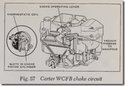
Fig. 57. This circuit operates in the same man ner as on other Carter carburetors. And like single and two banel carburetors, it is provided with a fast idle device and unloader mechanism, the operation of which has previously been described.
AFB SERIES
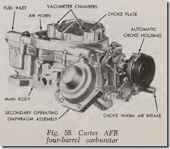
This carburetor, Fig. 58, while essentially the same as the WCFB, contains many new features, some of which are a new location for the step-up rods and pistons. The step-up rods, pistons and springs are accessible for service without remov ing the air horn, or the carburetor from the en gine. The venturi assemblies (primary and secon dary) are replaceable and contain many of the calibration points for both the high and low speed systems.
All the major castings of the carburetor are aluminum, with the throttle body cast integral with the main body. This allows an overall height reduction in the carburetor. The section contain ing the accelerator pump and integral choke is termed the primary side of the carburetor. The other side is the secondary. The five conventional systems used in the WCFB carburetor are also used in this unit.
AVS SERIES
Similar to the AFB, the four barrel AVS carbu retors, Fig. 59, have several novel features that make them different from the former. The AVS designation means, “Air Valve Secondary” and they have a spring loaded air valve located above the fuel -nozzles on the secondary side of the carburetor that provides very smooth response when the secondary throttles are opened. Instea of the built-in automatic choke of the AFB’s, this new series has a remotely locat ed temper ature sensing choke coil mounted on the intake mani fold over the exhaust crossover passage.
The primary side of the carburetor uses venturiclusters for fine fuel control in the idle and econ omy operating ranges. Fuel nozzles are pressed into the secondary side of the fuel bowl, eliminat ing protuberances in the secondary bores. This gives the carburetor exceptionally high air capac ity in the power ranges.
ABO SERIES
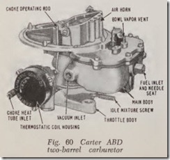
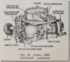
This carburetor, introduced in 1960, is a two barrel unit that contains the five conventional circuits. Like the AFB series, which it resembles, the air horn, float bowl and body, and throttle body are made of aluminum castings, Fig. 60 and 61.
A hot idle compensator, Fig. 61, is included in the low speed system. During long periods of idling with an extremely hot engine, the fuel in the carburetor bowl becomes hot enough to form vapors. These vapors enter the carburetor bores by way of the inside bowl vents. The vapors mix with the idle air and are drawn into the engine causing an excessively rich mixture and a loss in rpm or engine stalling. Also, the decrease in the density of the air caused by extreme high under hood temperatures can reduce the idle speed.
The hot idle compensator is calibrated to open under these temperature conditions, permitting additional air to enter the manifold below the throttle plates and mix with the fuel vapors to provide a more combustible mixture.
BBD & BBS SERIES
These carburetors are similar in design, the chief difference being that the BBS is a single barrel unit whereas the BBD is a dual barrel carburetor.
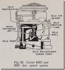
Each throat of the BBD carburetor supplies an air-fuel mixture to four specific cylinders. Thus it is essentially two carburetors in one housing. Each throat contains its own idle air bleed, high speed air bleed, idle orifice tube, main vent tube, main metering jet, metering port, idle port, idle mixture adjustment and throttle valve.
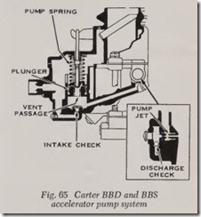
Metering of the fuel in the accelerating pump system on the BBD carburetor is accomplished by two accurately drilled orifices, one for each throat, in the discharge cluster. In the BBS carburetor, a replaceable accelerating pump jet is used.
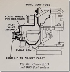
Figs. 62 and 65 illustrate the various systems. The Boat, low speed and pump systems operate in the conventional manner, but inasmuch as the high speed system is somewhat different, herewith is a description of its operation.
High Speed System
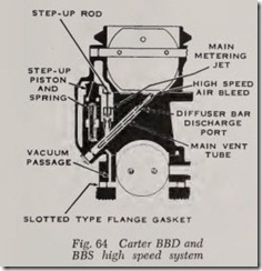
Fig. 64. When the engine is under a heavy load, suddenly accelerated, or operated at very high engine speeds, the step-up system supplies addi tional fuel through the diffuser bar discharge port. Fuel Bow through the fuel passage of the main metering jet is controlled by the movement of the step-up rod which in turn is moved by a spring and a vacuum-controlled piston. A vacuum pas sage to the intake manifold is provided for by a drilled passage in the carburetor body and throttle body, and a slotted Bange gasket.
Under normal driving conditions, manifold vacuum exerts a strong pull on the vacuum piston. This holds the piston down, keeping the step-up rod in the fuel passage of the main metering jet. Fuel then Bows around the rod, through the jet, and through the diffuser bar discharge port.
When manifold vacuum falls off, due to a heavy load, sudden acceleration, or very high engine speed, the spring moves the piston up, moving the step-up rod out of the main metering jet fuel passage. Additional fuel is then supplied to the engine.
Air is drawn through the high speed air bleed and mixes with the fuel surrounding the main vent tube. The mixture is then drawn from the diffuser discharge ports.
RBS SERIES
This carburetor uses a single lightweight alumi num casting with a pressed steel bowl. Adjust ments are readily accessible and most calibration points are located in the casting. Fuel pickups are located near the centerline of the carburetor bore to gain the benefits of a concentric bowl carbu retor, yet so located that engine heat being radi ated through the bore and conducted through the casting is not readily conducted to the fuel in the bowl. Vapor vents allow rapid dissipation of vapors to assure smooth idle and to minimize hard starting while engine is hot. A diaphragm con trolled step-up provides instantaneous response to engine demands. Figs. 66 to 70 illustrate the vari ous systems.
Float System
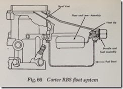
The float assembly extends around the metering portion of the casting to produce the effect of twin floats yet remains a single unit. It assures little or no change in float setting due to vibration or heat. The resilient needle seat has the ability to digest small foreign particles in the fuel to minimize leakage of fuel or flooding.
The bowl is vented to the inside of the air hom through a single tube which is calibrated to provide the correct air pressure above the fuel under all operating conditions, Fig. 66. An outside vent is provided for the bowl (around the pump plunger shaft) during idle and off idle operation to prevent fuel vapors under extreme heat condi tions being fed to the engine which might result in uneven idle. It also assures fast hot restarts.
Low Speed System
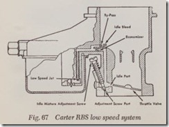
Fuel is metered as it enters the lower end of the low speed jet, Fig. 67, and flows up through the tube where air metered through the by-pass mixes with the fuel. The fuel and air then passes through the economizer to the idle bleed where a second metered amount of air is introduced. This mixture is discharged into the manifold through the idle port hole and the idle adjustment screw port.
During curb idle only a small amount of the idle port is exposed to intake manifold vacuum. As the throttle is opened slowly, more of the port is exposed to allow a calibrated increase in the amount of mixture fed to the engine.
High Speed System
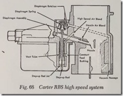
During part throttle operation the relatively high vacuum from the intake manifold is trans ferred through a passage to the upper surface of the spring loaded diaphragm assembly. Manifold vacuum opposing the calibrated spring, provides an economical mixture control to the engine at all times except when full power is requir ed. When the diaphragm is up, the larger diameter (lower end) of the step-up rod is in the jet to provide the economy mixture.
As the throttle is opened, manifold vacuum is decreased. The calibrated diaphragm spring then moves the diaphragm downward and the step-up rod, attached to the diaphragm, is lowered in the jet. The smaller diameter of the rod permits the metered increase in fuel How to provide for the additional power needs.
During acceleration the same action takes place to richen the mixture. However, the rod is raised in the jet as soon as terminal acceleration is reached when manifold vacuum indicates the need for a less rich mixture.
A vent tube with calibrated side holes is pressed into the high speed well around the step-up rod. A metered amount of air is fed from the bore of the carburetor to the annulus around the vent tube. This air passes through the side holes in the venttube to mix with the fuel before it flows through the nozzle to the air stream. This aerated fuel permits immediat fuel atomization as it emerges from the tip of the nozzle. This action is further helped by a second air bleed near the tip of the nozzle, Fig. 68.
Accelerator Pump System
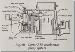
As the throttle is closed, the plunger is raised in the cylinder and fuel from the bowl flows into the cylinder through the check ball, Fig. 69. No air enters the cylinder due to the sealing action of the pump discharge needle in its seat.
As the throttle is opened, the spring on the connector link is compressed, which in turn pushes the plunger down in the cylinder. Fuel is forced past the discharge needle and out through the pump jet and into the air stream. During the discharge stroke the intake ball is on its seat to prevent fuel from flowing back into the bowl.
Choke System
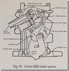
When the engine is cold, tension of the thermo static coil holds the choke valve closed, Fig. 70. As the engine is cranked, air pressure against the offset choke valve causes the valve to open slightly against the coil tension. Manifold vacuum applied to the choke piston also tends to pull the choke valve open. When the engine starts the choke valve assumes a position where tension of the coil is balanced by the pull of vacuum on the piston and force of the air stream against the offset choke valve. A fast idle cam, controlled by choke valve position, holds the throttle open the correct amount to provide a speed commensurate with engine temperature.
![Fig. 59 Carter AVS four-barrel carburetor_thumb[1] Fig. 59 Carter AVS four-barrel carburetor_thumb[1]](http://machineryequipmentonline.com/electric-equipment/wp-content/uploads/2020/06/Fig.-59-Carter-AVS-four-barrel-carburetor_thumb1_thumb.jpg)
