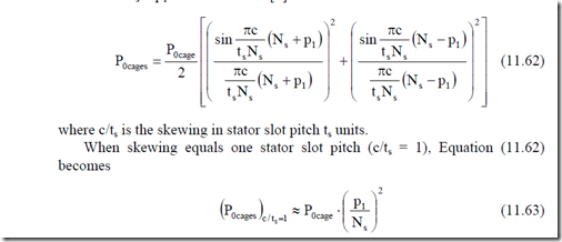
When the rotor slots are skewed and the rotor bars are insulated from rotor core, no interbar currents flow between neighboring bars through the iron core. In this case, the cage no-load stray losses P0cage due to first slot (opening) harmonics Ns ± p1 are corrected as [6]
in general, skewing reduces the stray losses in the rotor insulated (on no-load and on load) as a bonus from (11.60). For one stator pitch skewing, this reduction is spectacular.
Two things we have to remember here.
• When stray cage losses are almost zero, the rotor flux pulsation core losses are not attenuated and are likely to be large for skewed rotors with insulated bars.
• Insulated bars are made generally of brass or copper.
For the vast majority of small and medium power induction machines, cast aluminum uninsulated bar cages are used. Interbar current losses are expected and they tend to be augmented by skewing. We will treat this problem separately.
11.6. INTERBAR CURRENT LOSSES IN
NONINSULATED SKEWED ROTOR CAGES
For cage rotor IMs with skewed slots (bars) and noninsulated bars, transverse or cross-path or interbar additional currents occur through rotor iron core between adjacent bars.
Measurements suggest that the cross-path or transverse impedance Zd is, in fact, a resistance Rd up to at least f = 1 kHz. Also, the contact resistance between the rotor bar and rotor teeth is much larger than the cross-path iron core resistance. This resistance tends to increase with the frequency of the harmonic considered and it depends on the manufacturing technology of the cast aluminum cage rotor. To have a reliable value of Rd, measurements are mandatory.
To calculate the interbar currents (and losses), a few analytical procedures have been put forward [9, 6, 10]. While [9, 10] do not refer especially to the first slot opening harmonics, [6] ignores the end ring resistance.
In what follows, we present a generalization of [9, 11] to include the first slot opening harmonics and the end ring resistance.
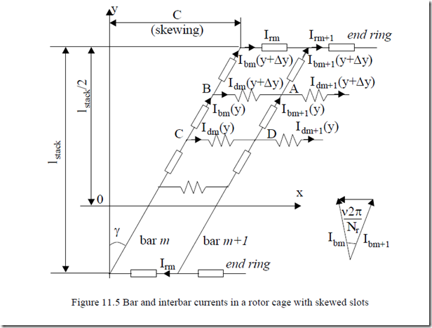
Let us consider the rotor stack divided into many segments with the interbar currents lumped into definite resistances (Figure 11.5). The skewing angle γ is
tan γ = c (11.64) lstack
What airgap field harmonics are likely to produce interbar currents? In principle, all space harmonics, including the fundamental, do so. Additionally, time harmonics have a similar effect. However, for chorded coil stator windings, the first slot harmonic Ns – p1 is augmented by the same stator mmf harmonic; Ns + p1 harmonic is attenuated in a similar way as shown in previous paragraphs.
Only for full-pitch stator windings, the losses produced by the first two 5th and 7th phase belt stator mmf harmonics are to be added. (For chorded coil windings, their winding factors, and consequently their amplitudes, are negligible).
At 50(60) Hz apparently the fundamental component losses in the crosspath resistance for skewed noninsulated bar rotor cages may be neglected. However, this is not so in high (speed) frequency IMs (above 300Hz fundamental frequency). Also, inverter fed IMs show current and flux time harmonics, so additional interbar current losses due to the space fundamental and time harmonics are to be considered. Later in this chapter, we will return to this subject.
For the time being, let us consider only one stator frequency f with a general space harmonic ν with its slip Sν.
Thus, even the case of time harmonics can be dealt with one by one changing only f, but for ν = p1 (pole pairs), the fundamental.
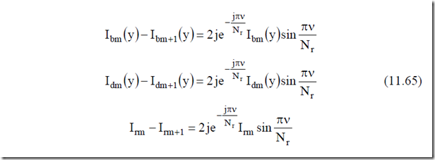
The relationship between adjacent bar and cross-path resistance currents on
Figure 11.5 are


