Continuity of Ring Circuit Conductors
( Stage One )
A ring circuit continuity test must be done to ensure that each phase, neutral and protective conductor is continuous and not broken at any point. If any conductor were broken then the load would not be properly shared by the conductors, possibly leaving one conductor overloaded and not adequately protected.
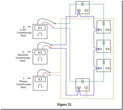
The ring circuit continuity test may be carried out as shown in Figure 22. The six conductors are disconnected from their respective terminals and the continuity of each of the three “rings” is checked in turn.
Readings 1 and 2 should be the same
Example 0.3 Ohms, the resistance of 43 metres of 2.5 mm2 cable.
The relationship between the resistance of 2.5 mm2 cable and 1.5 mm2 cable is 1.67. Reading 3 should be higher by a factor of 1.67.
Example 0.3 x 1.67 = 0.5 Ohms, resistance of 43 metres of 1.5 mm2 cable.
Related posts:
Counter-voltage in a Motor Armature
Amplifier Applications:Audio Amplifiers
Introduction to AC:Purely Resistive AC Circuits
Polyphase Motors
PNEUMATIC CONTROL FUNDAMENTALS:FEED AND BLEED SYSTEM
INTRODUCTION TO NETWORKING WIRED AND WIRELESS
Audio Amplifiers:Power BJTs vs Power MOSFETs as Amplifier Output Devices
Environmental sensors:Surveying and security
P–N Junction Diodes:testing P–N Junction Diodes
Relays, contactors, and motor starters:Mechanically Held Contactors and Relays
Engine Piston System part3
Speed control of d.c. Motors:Thyristor Speed Control of Separately-excited D.C. Motor
Relays, contactors, and motor starters:Electromagnet Construction
NETWORKING WIRED AND WIRELESS:TYPES OF NETWORKS
