Piston Pin & Rod Service
CHECK FOR LOOSE PISTON PINS
Before installing new rings, check the piston pins for looseness. If wear is considerable it can be felt. Hold the piston in one hand and grasp the rod with the other hand. Push and pull on the rod and also rock it back and forth in the plane of the piston pin. If there is noticeable play, the pin is too loose.
A more delicate test for wear in pin holes is to squirt some light oil on the end of the pin (after removing lock rings), wipe off the surplus and then note whether there is any motion in the oil film between pin and hole when the rod is rocked.
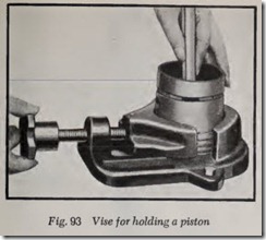
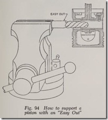
Instead of holding the piston in the hand it may be mounted in a piston vise, Fig. 93. Or the pin may be wedged onto an easy-out clamped verti cally in a vise, Fig. 94. If the piston pins are pressure lubricated through a rifle-drilled hole in the connecting rod, excessive oil consumption may result if the pins are loose in th eir piston holes, since the extra clearance between pins and piston permit extra oil to flow onto the cylinder bores.
PISTON PINS TOO TIGHT
Sometimes when pistons are removed, the pins will be found to be too tight, as indicated by the fact t at some effort is required to rock the piston on the rod. Usually this is caused by a gum or varnish deposit on the wearing surfaces. Remove the pins and clean the surfaces with a suitable solvent. If difficulty is experienced in removing the pins, heat the pistons in boiling water to soften the deposit.
REMOVE PISTON PINS
Before removing the piston pins, the pistons should be numbered by making light file marks on the inner edge of the bottom of the piston skirt. One mark for No. 1 piston, two marks for No. 2 piston, etc. Put these marks on the same side as the rod number and be careful to reassemble the rods and pistons accordingly.
The procedure in removing piston pins depends on whether the pin floats, or is locked to the piston or to the rod, or is a pressed fit.
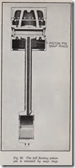
Full-Floating Pin-Remove the snap rings at either end of the pin, Fig. 95, by means of a pair of pliers with pointed jaws; or pry the snap rings loose with a screw driver. When the pin is reas sembled to the piston always use new snap rings.
Push out the pin with the fingers. If the pin is too tight to be removed by hand use a brass or copper drift. Insert the drift in the piston pin hole. Hold the piston in one hand and the drift in the other. Then gently pound the free end of the drift on a metal plate. If the piston is aluminum, pin removal is facilitated by heating the piston in hot water.
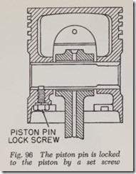
Set Screw Pin-Remove lock screw, Fig. 96, and then remove pin. A piston vise, Fig. 93, is recom mended when removing the lock screw, not only for convenience but also because it prevents pos sible distortion of the piston.
Oscillating Pin-Two types are shown in Figs. 97 and 98. In Fig. 97, the rod is clamped tight to the pin. Loosening the screw permits the removal of the pin.
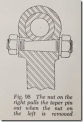
In Fig. 98 the lock screw has a tapered flat sur face which mates against a flat surface on the piston pin. To free the screw, loosen the nut on the left and tighten the one on the right until the pin is free. Then push or drive pin out of piston.
When reinstalling pin, be sure the flat spot is in the position shown. Loosen the nut on the right and tighten the left nut until lock screw is drawn up tight. Then tighten nut at right securely.
Press Fit Pin-Mount the piston and rod on a press and, using a suitable arbor, press the pin out of the rod. The press and arbor are used to install the pin in the rod. Any fit less than that which requires the use of a press is too loose.
PISTON PIN SIZES
Piston pins supplied by car makers are made in standard size and two or three oversizes. Over sizes of .003″ and .005″ are the most common. But some car makers offer ovcrsizes of .001″ and .003″ and .008″, or .003″, .005″ and .010″.
Piston pin manufacturers offer pins in standard size and oversizes of .003″ and .005″ with perhaps some additional oversizes for some of all makes of cars-.0015″ for example.
PISTON PIN FITS
Full Floating Pin-Alloy and cast iron pistons, light tap.
Oscillating Pin-Alloy piston, palm push.
Cast iron piston with bronze bushings, thumb push.
Cast iron piston without bushings, light thumb push.
Set Screw Pin-Alloy Piston: Set screw end, light tap; other end, thumb push.
Cast iron piston: Set screw end, light tap; other end, palm push.
Pin fits should be checked with the piston and pin at the same temperature. If the piston has been heated to remove the pin, allow it to cool off before checking the pin fit.
Diamond boring of pin holes is used by some manufacturers. Note that for each type of pin, the “push effort” is less with diamond boring than with honing or reaming.
Full Floating Pin-Alloy piston , palm push .
Cast iron piston, thumb push .
Oscillating Pin-Alloy piston, thumb push.
Cast iron piston with bronz e bush ings , thumb push.
Cast iron piston without bushings, light thumb push.
Set Screw Pin-Allo y and cast iron pistons :
Set screw end, light tap; other end, thumb pus h.
Piston pins that are press-fitted-and these are almost univer sal today-are approxim ately .001″ larger in diameter than the rod bore, and no bushing is used in the rod.
REAMING PIN HOLES
An expansion reamer should be used. The reamer is expanded or contracted by turning a nut on the end of the reamer.
Expansion reamers come in a range of sizes from 1/2″ diameter upwards by 1/16″ gradu ations.
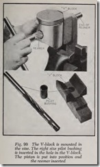
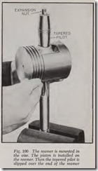
A piston can be reamed simply by clamping the reamer in a vise and rotating the piston on it. However, in order to insure a perfectly true hole the reamer should be piloted. Fig. 99 shows one design and Fig. 100 another.
When reaming a piston, be sure that both the reamer and the pin holes are clean. The reamer blades should be sharp. When a reamer becomes dull it should be returned to the factory for sharp ening. There is, of course, a limit to the number of times it can be sharpened.
The reamer should be kept amply lubricated with engine oil throughout the reaming process.
Measure the new pins with a micrometer to besure they are the correct size.
Reaming the piston hole to size requ ires a grad ual and cautious enlargem ent of the hole until it is j ust the right diameter.
The first step is to make a light cut for the pur pose of “fitting” the ream er to the hole. Make the cut through both pis ton bosses and then try the piston pin. It won’t go into the hole but at least it will give you some idea as to how much metal is still to be removed.
Expand the reamer a few tenths (ten-thou sandths), make another cut and try the pin again -and so on until the pin is the correct push fit. With each new cut expand the reamer less and less. The last cut might be only a fraction of a thousandth of an inch.
While fitting the pin to the piston, do not try to force it all the way into the boss. Inst ead, just try to insert the pin about 1/16″ into the boss. Tum the pin while pushing it in.
After the pin is fitted to the first piston, measure the reamer diameter with a micro met er. Then adjust the micrometer to read .0005″ less. Adjust the ream er to the micrometer and ream the re m aining pistons to this size. After this is done, fit each pin to its own piston by taking very light cuts until the fit is correct.
Be careful to keep each pin and its piston to gether. Either insert the pin in the piston or turn the piston upside down and put the pin insid e it.
REAMER FIXTURES FOR PISTON PINS
In Fig. 99, th e reamer is piloted in a V-block. There is a pilot bushing for each reamer size. To set up the fixture, select the correct size pilot bushing, insert it in the hole in the V-block, and mount the V-block in the vis e as shown . The V block insures that the piston is accurately lined up at right angles to th e pilot hole. The piston is held by one hand while the ream er is turned wit h the other.
In Fig. 100, the ream er is stationary and the piston is turned with both hands. The piston is placed on the reamer as shown and then the tapered pilot is slipped down over the top of the reamer. The nut for expanding the reamer is shown at the top. Every effort should be made by the hands to provide a purely rotary motion with out side thrust .
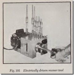
Fig. 101 illustrat es an electrically-driven reamer tool. The reamer is mounted in the chuck. The piston is slipped over the rea mer a nd stroked back and forth until the reamer runs free. Then th e reamer is expanded slightly, etc. In other words the method is similar in principle to hand reaming but much faster.
ROD BUSHINGS
New bushings may be required if standard size pins are to be installed. But if oversize pins are to be used, the rod bushings should be refinished oversize unless they are loose in their rod bores or badly scored, in which case new bushings should be installed.
The bushings in the rod may be in one piece, running the length of the rod bore, or two half length bushings may be used. Bushing walls may be of normal thickness or may have thin walls.
ROD BUSHINGS, REMOVE
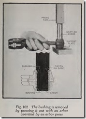
To remove a bushing, Fig. 102, select a drift of suitable diameter. The diameter of the shank of the drift should be slightly smaller than the rod bore. The diameter of the end of the drift should be a little less than the bushing bore.
Insert the drift in the rod and put the rod on the arbor press. The drift should be directly under the press ram and the side face of the rod should rest squarely on the surface of the support plate. Operate the ram lever to push the bushing out.
If an arbor press is not available the bushing may easily be removed as follows: Take the blade out of a hacksaw. Slip the blade through the bush ing and connect the blade to the hacksaw frame. Then saw a slot all the way through the bushing, after which it is a simple matter to drive it out of the rod.
ROD BUSHINGS, INSTALL
If the rod has an oil hole in it be sure to line up the oil hole in the bushing with the oil hole in the rod. Then press the bushing into the rod until it is flush with the sides of the rod. Check to be sure that the oil holes in bushing and rod are lined up.
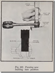
It is always good practice to use a special re placing drift, Fig. 103, when installing a bushing. The end of the drift should fit the bore of the bushing snugly so that when the bushing is pressed into the rod the snug fit will prevent distortion of the surface of the bushing bore.
If an arbor press is not available the bushing is easily installed as follows: File a slight bevel on th e leading edge of the bushing so that it can be started in the rod hole. Then place the rod and bushing between the jaws of a vise. Before closing the vise, make sure the bushing is square with the rod hole. Then push the bushing in the rod by turning the handle of the vise.
SWAGING ROD BUSHINGS
A special replacing drift is particularly desirable when installing thin-walled bushings.
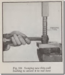
After a thin-walled bushing is installed it is likely to come loose in service unless it is forced tightly against the rod bore. This is done by a swaging tool, Fig. 104. The tool is slightly tapered, the diameter at the upper end being slightly larger than the bore of the bushing. The tool is forced down through the bushing, causing the metal to How until it presses so tightly against the rod bore that there is no danger of its coming loose. It also burnishes the bushing bore. Burnishing, by defini tion, is the rubbing of a hard tool over a surface to make it smooth. The burnishing, in this case, is a by-product of the all-important swaging opera tion. The tool is often called a burnishing tool although it is primarily a swaging tool.
After the thin-walled bushing is swaged, it should be finished to the required size by honing or reaming-preferably by a piston pin hole hon ing machine as the walls are considered too thin for reaming or hand honing tools.
HAND HONING PISTON PIN HOLES
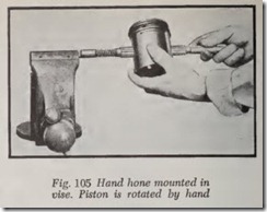
A hand hone is used in the same manner as a reamer. It can be mounted in a vise, Fig. 105, or the piston can be mounted in a fixture and the hone turned with a wrench. Use a fine abrasive cloth recommended by the maker of the tool. Like reamers, piston pin hones come in a range of sizes.
The tool is expanded in the same manner as a reamer. As with a reamer, the tool is expanded gradually during the honin g process until the piston pin just fits the hole. Both piston holes and rod bushings can be honed.
If the piston pin holes have to be enlarged more than .002″, it will save time to put th e hone in an electric drill which has a speed of about 300 to 500 rpm. Msmnt the drill in a vise with the hone hori zontal. The drill is conveniently started and stopped by a foot switch, Fig. 106, made for the purpose.
Clean the piston to be honed with gasoline. Select the proper oversize pin for each piston be fore honing (usually .003″ oversize ). Select the largest hone possible to insert in th e hole.
If only .001″ to .002″ is to be removed, a drill is hardly necessary because you may remove more metal than desired before you are aware of it. This is especially true on alloy pistons.
There are several effective methods of removing only a small amount of stock.
1. Clamp the driving end of piston hone in a bench vise, then revolve piston by hand, travers ing the piston back and forth.
2. Place the piston in a piston vise and rotate hone in the hole by means of any standard tap or reamer wrench.
3. Any hand brace can be used very handily by using same as in drilling with bit and brace.
For removing more stock in piston holes any portable electric drill with an approximate speed of 300 to 500 rpm. is recommended, or use a drill press.
Clamp portable drill in bench vise or use piston hone in drill press at the recommended speed. Insert piston hone in drill chuck, collapse suffi ciently to slide over piston hone. Expand hone snugly in piston hole (piston hone expanded into piston too tight will have a tendency to tear the abrasive cloth and wedge the hone in hole and will not cut). Start the drill and traverse piston back and forth 4″ beyond the edge of abrasives on either end of piston hone. After honing for a few seconds the drill will run free. Stop the drill, remove piston from hone without moving the graduated adjusting screw and check the hole in the piston.
After each run of the piston hone (which is usually 30 to 45 seconds) reverse the piston end for end and hone as before: When the piston is honed to size so that the piston pin just enters snugly and you notice a slight difference in one end of piston, enter piston hone into the small end of piston, and traverse back and forth with only a short stroke. Hone this end of piston to the same size as the other end, using the piston pin as a plug gauge. This method of honing will produce a straight round hole in both ends of the piston.
IMPORTANT: Use a dry cloth or bristle brush to clean the abrasives after each run. Do not use a wire brush or sharp abrasive for cleaning, as they reduce the life of abrasives. After each run when abrasives have been cleaned, slide piston on hone, release lock screw and expand graduated screw two graduations. Proceed as before. The expand ing of two graduations is very important: more than two graduations at each run will not remove any more stock, but will shorten the life of abra sives.
