FORD TAV SYSTEM
Temperature Activated Vacuum
This system selects either the carburetor spark port vacuum, or the carburetor EGR port vacuum as a function of outside ambient air temperature.
The EGR system can be used in addition to the TAV system, although systems work independently of each other.
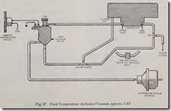
The TAV system, Fig. 97, consists of an ambient temperature switch, a three-way vacuum valve, and an external inline vacuum bleed. The three way vacuum valve is used to select the carburetor vacuum source that is supplied to the distributor vacuum advance mechanism. The ambient tem perature switch provides the switching circuit to determine which vacuum source will be selected as a function of outside air temperature. The in line vacuum bleed function is to purge the vacuum line in the TAV system of any excessive gasoline vapors.
The basic difference between a TAV system and the standard IMCO system is the selective control feature provided by TAV system for distributor vacuum advance as a function of outside air tem perature.
When the ambient air temperature is above 60 degrees F. the three-way vacuum valve is ener gized, therefore the EGR vacuum is controlling the distri:butor advance. When the ambient air tem perature is below 49 degrees F. the three-way vac uum valve is de-energized, therefore the spark port vacuum is controlling the distributor advance.
NOTE: The TAV system controls spark advance below 49 degrees F. while the EGR system con trols spark advance above 60 degrees F.
FORD CTAV SYSTEM
Cold Temperature Activated Vacuum
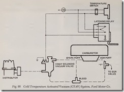
This system operates basically the same as the TAV system previously discussed except that a latching relay, Fig. 98, has been added. The latch ing relay, activated by temperature switch closing remains energized regardless of temperature switch position which prevents system cycling due to minor ambient temperature changes.
The temperature switch energizes the three-way vacuum valve and latching relay when ambient temperature is above 65° F. When ambient tem perature is below 49° F., the system is inoperative and the distributor diaphragm and EGR valve re ceives vacuum directly from its respective carbu retor ports.
FORD HCV SYSTEM
Vacuum Operated Exhaust Heat Control Valve
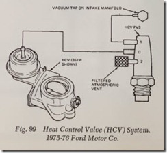
Used on all1975 vehicles except those equipped with the 2300cc and VS-460 engines and some 1976 models this system, Fig. 99, provides quick induc tion system warm-up for better cold engine fuel
vaporization.
A vacuum operated heat control valve mounted between the exhaust manifold and pipe, directs a portion of the exhaust gases through the intake manifold during engine warm-up. On cold starts, manifold vacuum is directed to the heat control valve ( HCV) through the top two ports in HCV PVS (ported vacuum switch), closing the HCV. When engine coolant temperature reaches a pre determined value, the PVS closes off vacuum and vents the PVS allowing the HCV to close under spring tension. The three PVS valves used may be identified as follows:
| PVS Body Color | Opening Temp. ( ° F.) |
| Black | 92-98 |
| Blue | 125-131 |
| Purple |
157-163 |
CATALYTIC CONVERTERS
The catalytic converter serves two purposes: it permits a faster chemical reaction to take place and although it enters into the chemical reaction, it remains unchanged, ready to repeat the process. The catalytic converter combines hydrocarbons (HC) and carbon monoxide (CO) with oxygen to form water ( H20) and carbon dioxide ( C02 ).
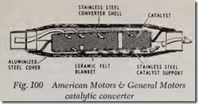
The catalyst is structured in the form of pellets,Fig. 100 (American Motors and General Motors),
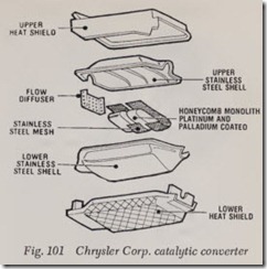
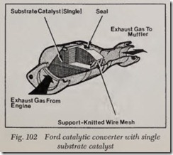
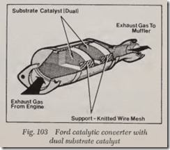
or a honeycomb monolithic composition, Fig. 101 (Chrysler Corp.) and Figs. 102 and 103 (Ford). The catalyst consists of a porous substrate of an inert material, coated with platinum and other noble metals, the catalytically active materials.
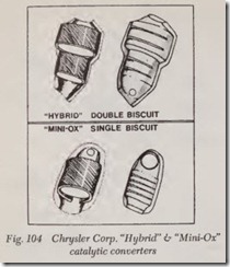
1977 Chrysler Corp. vehicles use two mini oxidation catalytic converters in conjunction with the main underfloor converter. Their main purpose is to initiate exhaust gas oxidation before the gases reach the underfloor converter. The «mini-ox”, Fig. 104, is a single biscuit catalytic converter and is shaped so that only one small biscuit can fit inside the can. The ”hybrid” converter, Fig. 104, utilizes a large biscuit and a small biscuit. A Power Heat Control Valve is used to increase the flow of ex haust gases through the left-hand exhaust mani fold to rapidly bring the mini-catalyst up to op erating temperature.
1977 American Motors California models use monolythic type warm up converters located ahead of the pellet type converter. Vehicles with 6 cylinder engines use one warm up converter and vehicles with 8 cylinder engines use two warm up converters.
This device, located in the exhaust system be tween the exhaust manifold and muffier, requires the use of heat shields, in some cases, due to its high operating temperatures. The heat shields are necessary to protect chassis components, passenger compartment and other areas from heat related damage.
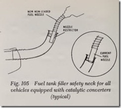
A smaller fuel filler tube neck is incorporated to prevent the larger service station pump nozzle, used for leaded fuels, from being inserted into the filler tube, thereby preventing system contamina tion, Fig. 105.
CAUTION: Since the use of leaded fuels con taminates the catalysts, deteriorating its effective ness, the use of unleaded fuels is mandatory in vehicles equipped with catalytic converters. The catalytic converter can tolerate small amounts of leaded fuels without permanently reducing the catalyst’s effectiveness.
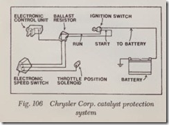
Most Chrysler Corp. vehicles equipped with catalytic converters have a catalyst protection sys tem, Fig. 106. This system maintains engine idle above 2000 rpm during certain conditions to pro tect the catalyst from high temperatures. Also this system prevents complete throttle closure at high engine rpm, in turn reducing the catalyst tem perature under deceleration conditions.
