CAUTION: The utmost care should be exercised when using a torch in the area of the fuel evapora tion system as an open flame near these hoses may cause a fire and ultimate explosion.
Also installation of a fill cap from a non-emission fuel tank will render the system inoperative, since the non-emission fill cap is vented and the system must be sealed to function properly. Also if a non vented fill cap is installed on a conventional tank the result will be a serious deformation or a total collapse of the fuel tank.
NOTE: Vapor line hoses used in these systems are made from a special rubber material. Bulk service hoses are available for service and will be marked “EVAP.” Ordinary fuel hoses should not be used as they are subject to deterioration and may clog system.
Two different systems are used to accomplish a reduction of evaporative losses to less than six gallons a day. 1971-77 American Motors, 1972- 77 Chrysler and all General Motors store the fuel vapors in a carbon-filled canister before burning them in the engine. 1967-71 Chrysler and 1967-70 American Motors store the vapors in the crank case. Ford fits refined versions of both systems.
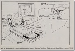
On pre 1971 American Motors vent system, fuel vapors are routed from the tank, through a check valve and connecting lines to the valve cover of the engine, Fig. 1. On V8 engines, the line is routed to the left valve cover. Vapors are then drawn into the PCV system and burned along with the normal air-fuel mixture. Most fuel tanks in corporate an integral fuel expansion tank to pro vide an air displacement area for normal fuel expansion, unless the tank itself is designed to provide an adequate air displacement area for fuel expansion.
A check valve is included to prevent the flow of liquid fuel to the valve cover under all operat ing conditions.
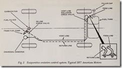
The 1971-77 engines incorporate a “Fuel Vapor Storage (Charcoal) Canister,” Figs. 1 and 2. This canister contains activated charcoal granules which absorb and store the fuel tank vapors until they are drawn into the intake manifold through the PCV system on six cylinder engines or the carburetor air cleaner on V8 engines.
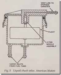
On ruel tanks without a fuel expansion tank, a hquid check valve, Fig. 3, is used to prevent hquid fuel from entering the vapor hnes.
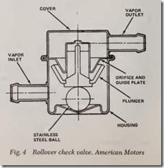
Two rollover check valves are used on 1977 vehicles to prevent fuel spillage in case of a roll over accident. The check valve located in the vent line, Fig. 4, has a steel ball loose within its guides which drops to seat a plunger when the unit is in verted. The check valve located in the fuel filler cap has a steel ball in a plastic housing which drops in its orifice when the vehicle is tipped sufficiently.
The filler cap includes a two-way relief valvewhich is closed to atmosphere under normal op-erating conditions and opens only when an abnor mal pressure or vacuum develops within the tank. It is normal to occasionally encounter an air pres sure release when removing the filler cap.
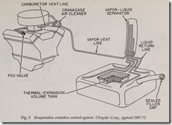
In the 1967-71 Chrysler system, fuel vapors from both the sealed gasoline tank and the carburetor are fed to the crankcase rather than the canister, Fig. 5. When the engine is running, the vapors are purged to the intake manifold through the existing crankcase ventilation system.
Chrysler’s liquid-vapor separator is a vertically mounted 2-in. diameter steel tube containing four tank vent lines and a line to the crankcase. Line heights are different, with the crankcase vent be ing the highest. This vent also has a small orifice to further inhibit liquid fuel transfer.
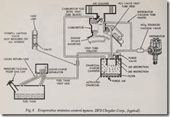
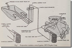
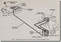
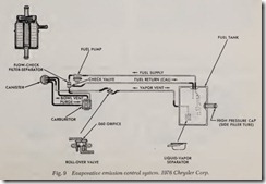
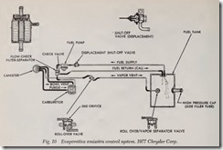
In the 1972-77 Chrysler system, Figs. 6 thru 10,when fuel tank is filled to the base of the filler tube, vapors can no longer escape, they become trapped above the fuel. Vapor flow through the vent line is blocked by the limiting valve; and the filler tube is blocked by fuel preventing more fuel to enter the tank. At any time pressures in the tank rise above operating pressure of the limiting valve, about 3f psi, the valve opens and allows vapors to flow forward to the charcoal canister. Due to the configuration of the fuel tank on some models and all station wagons, vapor separator tanks are not required. The charcoal canister is a feature on all models for the storage of fuel vapors from the fuel tank and carburetor bowl. A vacuum port located in the base of the carburetor governs vapor flow to the engine. On some models, each corner of the fuel tank is vented and each of the hoses from these vents is connected to a vapor separator. A tube from the separator leads to the charcoal canister. Evaporated fuel vapor from the fuel tank, flows through the separator to the canister. The canister used in 1973-77 vehicles will have three hoses and no purge valve. The purge valve previously located on top of the canister has been eliminated by using an additional ported vacuum connection on the carburetor for purging the can ister. This utilizes the throttle plates of the car buretor as purge valve. This system will improve hot idle quality by eliminating canister purging dming idle. Some limited production, High Per formance vehicles will continue to use the earlier type two stage canister which utilizes an integral purge valve. This canister can be identified by four hose connections while the new type canister uses only three. In order to meet Federal Saf ety Standards, a rollover check valve is used on 1976- 77 vehicles to prevent fuel spillage in the event of an accidental rollover.
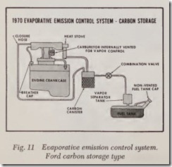
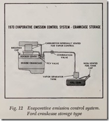
Ford refines the ECS designs by fitting a 3-way valve between the separator and the vapor storage, Figs. 11 and 12. Fuel vapor is transported either to a carbon canister or the engine crankcase, de pending on the year of the vehicle and/or engine application. It is then drawn into the engine, from the carbon canister to the air cleaner, or from the crankcase through the PCV system.
The fuel tank is designed to limit the fill ca pacity to provide space for normal fuel expan sion. A separate tank is located above the fuel tank to separate vapor from liquid and prevent any liquid from entering the system.
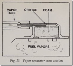
A combination valve on the forward side of the fuel tank isolates the fuel tank from engine pres sures and allows vapor to escape from the sepa rator to the carbon canister. It also relieves ex cessive fuel tank pressure and allows fresh air to be drawn into the tank as fuel is used.The fill control vent system which provides positive control of fuel height during fill opera tions is made possible by the design of the filler pipe and by vent lines within the filler neck or fuel tank. This system is designed so that about 10% of tank capacity will remain empty when the tank is filled. This space allows for thermal fuel expansion and temporary storage of fuel vapors. The pressure and vacuum relief valve system op erates through the use of a sealed fill cap with a built-in pressure and vacuum relief valve. Under normal operating conditions, the valve opens to relieve pressure when it exceeds %: to Hpsi. When fuel tank vacuum reaches inch mercury maxi mum, the valve opens allowing air to enter the system. The vapor vent and storage system used on vertically mounted fuel tanks consists of a vapor separator, Fig. 13, mounted on the upper most surface of the tank. The empty space at the top of the tank provides adequate breathing space for the vapor separator. Horizontally mounted fuel tanks use a raised mounting section for the vapor separator. This raised section provides additional breathing space for the vapor separator since the space allowed for thermal expansion of fuel is not as deep as it is on vertically mounted tanks.
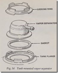
The vapor separator which acts as a baffle to prevent fuel from entering the charcoal canister, Fig. 14, consists of a small hole in the outlet con nected to the vapor tube plus open cell foam to separate liquid fuel and fuel vapors. The fuel va pors in the tank go through the opening in the vapor separator and into the vapor tube. A fuel vapor return system is used on some engines tore duce the amount of fuel vapor entering the carbu retor. It consists of a fuel vapor separator installed in the fuel supply line between the pump and carburetor and a one piece vapor return line from the separator to the fuel tank. Fuel vapors are col lected in the separator and routed to the fuel tank where they recondense or are contained by the evaporative emission control system.
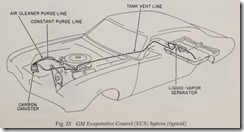
In the GM Evaporative Control System ( ECS ), vaporized fuel is fed from the sealed gas tank through a liquid-vapor separator to the storage canister, Fig. 15. There, when the engine is not
running, the fuel is absorbed by the activated charcoal. When the engine is running, purge air Rows through the canister carrying the fuel to the engine where it is burned. Constant purging of
vapors f rom the canister is accomplished through a calibrated orifice in the canister center connection to th e PCV hose andjor the air cleaner snorkel. All GM carburetor Roat bowls are internally vented to trap bowl losses in the intake manifold, air cleaner and can ister lines. Some carburetors have a vent switch in the bowl to divert the vapors to the canister. Other carburetors are insulated to re duce bowl temperatures.
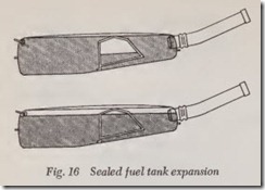
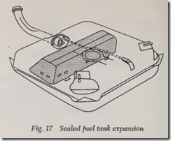
All fuel tanks include a fill limiting baffle which allows space for normal fuel expansion which can be as much as three gallons on a hot day, Figs. 16 and 17. To prevent damage to the tank from ex cessive internal or external pressure resulting from the closed system, a filler cap is used, which in cludes a two-way relief valve which opens only when an abnormal pressure or vacuum develops within the tank.
A liquid vapor separator is provided to prevent liquid fuel from entering the system. Liquid fuel entering the separator is spilled back into the tank while raw fuel vapor is passed into the lines.
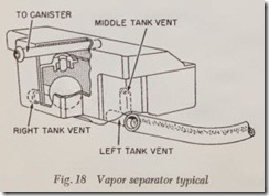
Three expansion vents connect the tank with the liquid-vapor separator. The vents are positioned so that one is always above the liquid whatever the vehicle’s attitude. The separator, Fig. 18 con tains a ball float that rises, closing a needle check valve to prevent liquid fuel from passing to and overloading the carbon.
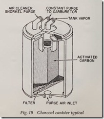
Fuel vapor enters the canister at a small cylin drical chamber above the charcoal. If the engine is running, most vapors are immediately drawn off to the carburetor. The excess is trapped by the activated charcoal. When engine speed is above idle, air is drawn through the carbon, where it picks up the trapped fuel, and is fed to the air cleaner snorkel, Fig. 19.
That then is the position regarding exhaust and evaporative emissions. Changes are occurring ev ery day, and undoubtedly will continue to occur frequently for some time to come.
It is important, therefore, for the mechanic to watch fpr changes and to follow absolutely the specifications for adjustment and tune up which are plainly displayed under the hood of every car made since about 1968. Really accurate settings are absolutely essential for correct operation of engine and exhaust emission equipment.
