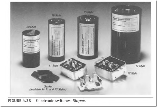
The electronic start switch is a very popular replacement switch. Many motor manufacturers use this switch on their single-phase motors. Many junked single-phase motors could have been repaired with these switches, for a fraction of their replacement cost.
Electronic switches operate on the same principle as the potential relay.
This switch has voltage-sensing circuitry that switches off the start winding at a preset voltage. If the motor is overloaded or if there is a power interruption, the switch will reconnect the start winding at about 50 percent of synchronous speed.
Electronic switches are made for split-phase, capacitor-start, and twovalue capacitor motors. The same switch will control two-, four-, and six-pole motors. The only two requirements are that the switches have the right voltage rating and a large enough ampere rating.
The electronic switch will control any size motor that draws less than the switch’s ampere rating. (It’s very important that the ampere rating of the switch is as high as or higher than the motor’s nameplate ampere value.)
The cutout voltage values for 115-volt switches are 130, 147, and 165 volts. The cutout voltage values for 230-volt switches are 260 and 310 volts.
To find the required voltage, run the motor with no load on its rated voltage. Isolate the start winding from the line and record the voltage across it (T5 and T8). Select a switch that has a voltage value rating closest to 80 percent of the voltage found across T5 and T8. (Be sure the ampere rating of this switch is equal to or higher than the motor’s full load amperes.)
If the motor has a coasting-type load, (for example, a radial arm saw), a special resistor is used to prevent high voltage from destroying the electronic components during coastdown.
These switches replace the switch contacts and centrifugal devices for all
split-phase, capacitor-start, and two-value capacitor motors.
Time-Delay Electronic Start Switch
Time-delay electronic start switches shut off the start winding at a predetermined time. They are available in 1/3 second, 1 /2 second, and I second delay time. If the motor stalls or doesn’t get up to speed by the time the contacts open, the motor must be restarted to reconnect the start winding.
(If the thermal device doesn’t trip, the run winding will be destroyed.)
It is possible to plug (reverse while running) the motor with this switch. (A motor with a centrifugal device has to slow enough for the contacts to close before it can be reversed.)
The same switch will operate capacitor-start, split-phase, and two-value capacitor-start motors of two to eight poles. Horsepower ratings are from the smallest motor to 5 hp. The voltage ratings of these switches are 115 and 230 volts. Ampere ratings are 30 amperes and below.
These switches will replace a motor’s stationary contacts and centrifugal device.
Heat-Activated Start Switch
Many sealed refrigeration compressors have heat-activated start switch controls (Fig. 4.39). When the motor starts, the start-winding current flows through a bimetallic strip. The bimetallic strip quickly heats, bends, and opens the start-winding contacts.
A small heat element next to the bimetallic strip is connected parallel to the contacts and in series with the start winding. It bypasses the start switch contacts. After the switch contacts open, a small current through the start winding heats the element and keeps the bimetallic strip hot. As the motor runs, the bimetallic strip stays hot enough to keep the switch contacts open.
The motor won’t start if it’s restarted before the bimetallic strip cools and reconnects the start-winding contacts. A thermal protective device should trip and shut off the power. The thermal protective device is usually self-resetting, and by the time it cools off enough to restart the motor, the heat-activated start switch has reset.
Current Relay Start Switch
The current relay start switch is used on single-phase motor applications where a stationary switch and centrifugal device aren’t practical. (A submersible deep well water pump is a good example.) This application requires that the motor and pump be pulled up from the bottom of the well to be serviced if the start winding controls are mounted in the motor.
A current relay start method makes it possible to locate the start switch contacts and capacitor where they are accessible. (Capacitors and switch contacts need servicing more frequently than the rest of the motor.) Another advantage the current relay has is that only three cables are needed to power the pump motor and control the start winding.
Current Relay Start Switch Connections
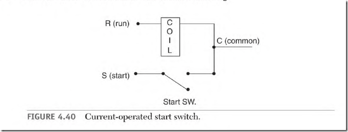
The current relay switch in Fig. 4.40 is connected to the three motor terminals marked C (common), S (start), and R (run). The common lead (C) connects to one side of the start winding and one side of the run winding. The other side of the run winding (R) is in series with the relay coil and line 2. The start winding (S) is in series with the switch contacts, the capacitor, and line 2.
Function of the Current Relay Start Switch
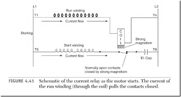
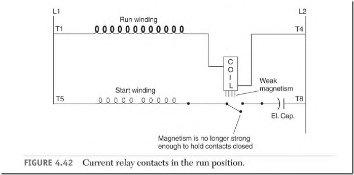
The run-winding current continuously flows through the current relay’s coil. When the motor starts, high run-winding current pulls the (normally open) start contacts closed (Fig. 4.41). The start-winding circuit is now connected to line 2, and the motor starts. As the rotor accelerates, ampere flow becomes lower in the run-winding and relay coil. At 75 to 80 percent of synchronous speed, the relay coil can no longer hold the contacts closed. The contacts drop open and the start winding is disconnected. The run winding will now pull the rotor up to full speed (Fig. 4.42).
The relay coil’s ampere rating must fit a motor’s run-winding ampere demand. A motor that’s too small won’t draw enough amperes to close the switch contacts. A motor that’s too large will draw so many amperes that the contacts won’t drop open.
Most current relay switch contacts fall open by gravity. For this reason, the relay must not be mounted at an angle. Even a slight tilt will prevent the contacts from falling open. All-angle current relays have spring-loaded contacts. A relay stamped “this side up” isn’t all-angle.
A pulsing-type load may cause the contacts to close every time the load peaks. This overheats the start winding and the capacitor and causes the switch contacts to prematurely fail.
