DIGITAL CLOCKS
Knowing the exact time has become more important today. We have to catch trains that leave at odd times. Radio and television programs start at precise times. Many of the jobs people do involve the precise timing of manufacturing processes, cooking, driving, and so on. Clocks and watches, which not long ago were luxuries, are essential to our lives. Fortunately a new family of clocks and watches has been developed. These rely not on pendulums or springs for their accuracy but on an electric current. A current passing through a quartz
crystal produces regular waves which can be made to show time either in figures, as in a digital watch, or on the usual clock face. Quartz crystal clocks and watches are accurate to within a few seconds a year.
In analog clocks the hands move continuously. In doing so they initiate, or simulate the passage of time. In digital clocks the time is shown in steps, as a digital process. No times are displayed between one step and the next.
DIGITAL CLOCK
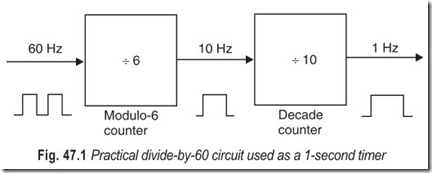
An interesting and common use of counters is for frequency division. An example of a simple system using a frequency divider is shown in Fig. 47.1. This system is the basis for an electric clock. The 60 Hz input frequency formed into a square wave is divided by 60, and output will be one pulse per second (1 Hz). This is a seconds timer.
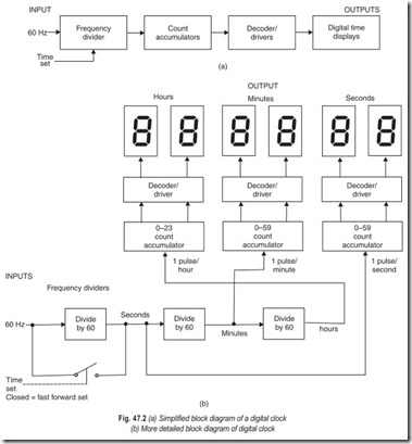
Various counters are the heart of a digital clock system. Figure 47.2 (a) is a simple block diagram of a digital clock system. Many clocks use 60 Hz as their input or frequency standard. This frequency is divided into seconds, minutes and hours by the frequency divider section of the clock. The one-per-second, one-per- minute and one-per-hour pulses are then counted and stored in the count accumulator section of the clock. The stored contents of the count accumulators (seconds, minutes, hours) are then decoded and the correct time is shown on the output time displays. The digital clock has the typical elements of a digital system. The input is the 60 Hz alternating current. The processing takes place in the frequency divider, count accumulator, and decoder sections. Storage takes place in the count accumulators. The control section is illustrated by the time-set control, as shown in Fig. 47.2 (a). The output section is the digital time display.
All systems consist of logic gates, flip-flops, and subsystems. The diagram in Fig. 47.2 (b) illustrates how subsystems are organised to display time in hours, minutes, and seconds. This is a more detailed diagram of a digital clock. The input is still a 60 Hz signal. The 60 Hz may be from the low voltage secondary coil of a transformer. The 60 Hz is divided by 60 by the first frequency divider. The output of the first divide-by-60 circuit is 1 pulse per second. The 1 pulse per second is fed into an up counter that counts from 00 though 59 and then resets to 00. The seconds counters are then decoded and displayed on the 2 seven-segment LED displays at the upper right, Fig. 47.2 (b).
Consider the middle frequency-divider circuit in Fig. 47.2 (b). The input to this divide-by-60 circuit is 1 pulse per second, the output is 1 pulse per minute. The 1 pulse per minute output is transferred into the 0
to 59 minutes counter. This up counter keeps track of the number of minutes from 00 through 59 and then resets to 00. The output of the minutes counter accmmulator is decoded and displayed on the two 7-segment LEDs at the top centre, Fig. 47.2 (b).
Now for the divide-by-60 circuit on the right in Fig. 46.2 (b). The input to this frequency divider is 1 pulse per minute. The output of this circuit is 1 pulse per hour. The 1 pulse per hour output is transferred to the hours counter on the left. This hours count accumulator keeps track of the number of hours from 0 to 23. The output of the hours count accumulator is decoded and transferred to the 2 seven-segment LED displays at the upper left, Fig. 47.2 (b). This is a 24-h digital clock. It easily could be converted to a 12-h clock by changing the 0 to 23 count accumulator to a 1 to 12 counter.
For setting the time, a time-set control has been added to the digital clock in Fig. 47.2 (b). When the switch is closed (a logic gate may be used) the display counts forward at a fast rate. This enables you to set the time quickly. The switch bypasses the first divide-by-60 frequency divider so that the clock moves forward at 60 times its normal rate. An even faster fast-forward set could be used by bypassing both the first and the second divide by-60 circuits. The latter technique is common in digital clocks.
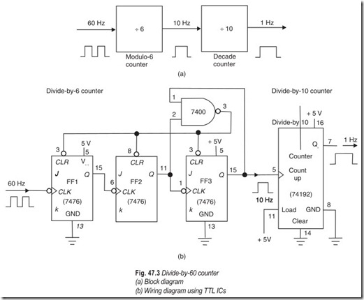
Figure 47.3 (a) is a block diagram of how a divide-by-60 frequency divider might be organised. A divide-by-6 counter is feeding a divide-by-10 counter. The entire unit divides the incoming frequency by 60. In this example the 60 Hz input is reduced to 1 Hz at the output.
The detailed wiring diagram for a divide-by-60 counter circuit is drawn in Fig. 47.3 (b). The three JK flip-flops and NAND gate form the divide by-6 counter while the 74192 decade counter performs as adivide-by-10 unit. If 60 Hz enters at the left, the frequency will be reduced to 1 Hz at the output QD of the 74192 counter.
The seconds and minutes count accumulators in Fig. 47.2 (b) are also counters. The 0 to 59 is a decade counter cascaded with a 0 to 5 counter. The decade counter drives the 1s place of the displays. The mod-6 counter drives the 10s place of the displays. In the same manner the hours count accumulator is a decade counter cascaded with a 0 to 2 counter. The decade counter drives the 1s place in the hours display. The mod-3 counter drives the 10s place of the hours display.
In many practical digital clocks the output may be in hours and minutes only. Most digital clocks are based upon one of many inexpensive ICs. Large-scale-integrated clock chips have all the frequency dividers, count accumulators, and decoders built into a single IC.
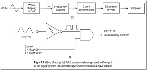
A wave-shaping circuit has been added to the block diagram in Fig. 47.4 (a). The IC counters that make up the frequency-divider circuit do not work well will a sine wave input. The sine wave has a slow rise time that does not trigger the counter properly. The sine wave input must be converted to a square wave. The wave-shaping circuit changes the sine wave to a square wave. The square wave will now properly trigger the frequency-divider circuit (Fig. 47.4b).
LSI DIGITAL CLOCK
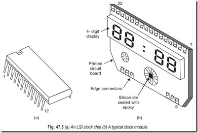
The LSI clock chip forms the heart of modern digital timepieces. These digital clock chips are made as monolithic MOS ICs. Many a times, the MOS LSI chip, or die, is mounted directly on the PC board of a clock module. The tiny silicon die is sealed under an epoxy coating. Examples of the two packaging methods are shown in Fig. 47.5. An MOS LSI clock IC packaged in a 24 pin DIP is shown in Fig. 47.5 (a). Pin 1 of the IC is identified in the normal manner (pin 1 is immediately counter clockwise from the notch). A National semiconductor clock module is sketched in Fig. 47.5 (b). The back is a PC board with 22 edge connectors.
The numbering of the edge connectors is shown. A four digit LED display is premounted on the board with all connections intact.
Some clock modules have some discrete components and a DIP clock IC mounted on the board. The clock module in Fig. 47.5 (b) has the tiny silicon chip, or die, mounted on the PC board. It is sealed with a protective epoxy coating.
EXERCISES
Descriptive Questions
1. With the help of a block diagram explain the working of a seconds timer.
2. Draw the detailed block diagram of a digital clock and explain its working.
3. Draw the block diagram and explain the working of a divide-by-60 counter.
4. Why wave-shaping is required? Explain its significance in digital clocks.
5. Explain the working of typical LSI clock chip.
Fill in the Blanks
1. An interesting use of counters is for frequency …………………………. in digital clocks.
2. Many clocks use…………………………. as their input or frequency standard.
3. The digital clock has the typical elements of a digital…………………………. .
4. For setting the time a…………………………. is added to the digital clock.
5. When the time set switch is closed, the clock moves forward at…………………………. its normal rate.
6. The sine wave has a slow…………………………. which does not…………………………. the counter properly.
7. The wave-shaping circuit changes the sine wave to a …………………………. .
ANSWERS
Fill in the Blanks
|
1. division |
2. 60 Hz |
3. system |
|
4. time set control |
5. 60 times |
6. rise time, trigger |
|
7. square wave |
