Many of the electrical control devices de scribed in this unit can be connected in an inter locking system so that the final operation of one or more motors depends upon the electrical posi tion of each individual control device. For exam ple, a float switch may call for more liquid but will not be satisfied until the prior approval of a pres sure switch or time clock is obtained. To design, install, and maintain electrical controls in any elec trical or mechanical interlocking system, the elec trical technician must understand the total opera tional system and the function of the individual components. With practice, it is possible to trans fer knowledge of circuits and descriptions for an understanding of additional similar controls. It is impossible-in instructional materials-to show all possible combinations of an interlocking con trol system. However, by understanding the basic functions of control components and their basic circuitry, and by taking the time to trace and draw circuit diagrams, difficult interlocking control sys tems can become easier to understand.
STARTING AND STOPPING
In starting and stopping a motor and its as sociated machinery, there are a number of condi tions that may affect the motor. A few of them are discussed here.
Frequency of Starting and Stopping
The starting duty cycle of a controller is an important factor in determining how satisfactorily the controller will perform in a particular applica tion. Magnetic switches, such as motor starters, relays, and contactors, actually beat themselves apart from repeated opening and closing thou sands of times. An experienced electrician soon learns to look for this type of component failure when trouble shooting any inoperative control panels. NEMA standards require that the starter size be derated if the frequency of start-stop, jog ging, or plugging is more than 5 times per minute. Therefore, when the frequency of starting the con troller is great, the use of heavy duty controllers and accessories should be considered. For stan dard duty controllers, more frequent inspection and maintenance schedules should be followed.
Light or Heavy Duty Starting
Some motors may be started with no loads and others must be started with heavy loads. When motors are started, large feeder line distur bances may be created which can affect the elec trical distribution system of the entire industrial plant. The disturbances may even affect the power company’s system. As a result, the power compa nies and electrical inspection agencies place certain limitations on “across-the-line” motor starting.
Fast or Slow Start (Hard or Soft)
To obtain the maximum twisting effort (torque) of the rotor of an ac motor, the best st art ing condition is to apply full voltage to the motor terminals. The driven machinery, however, may be damaged by the sudden surge of motion . To prevent this type of damage to machine s, equip ment, and processed material s, some controllers are designed to start slowly and then increase the motor speed gradually in definite steps. This type is often used by power companie s and inspection agencies to avoid electrical line surges.
Smooth Starting
Although reduced electrical and mechanical surges can be obtained with a step-by-step motor starting method, very smooth and gradual starting will require different controlling methods. These are discussed in detail later in the text.
Manual or Automatic Starting and Stopping
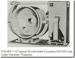
While the manual starting and stopping of machines by an operator is still a common prac tice, many machines and industrial processes are started and restarted automatically. These auto matic devices result in tremendous savings of time and materials. Automatic stopping devices are used in motor control systems for the same rea sons. Automatic stopping devices greatly reduce the safety hazards of operating some types of ma chinery, both for the operator and the materials being processed. An electrically operated, me chanical brake is shown in figure 1-13. Such a brake may be required to stop a machine’s motion in a hurry to protect materials being processed or people in the area.
Quick Stop or Slow Stop
Many motors are allowed to coast to a stand still. However, manufacturing requirements and safety considerations often make it necessary to bring machines to as rapid a stop as possible. Au tomatic controls can retard and brake the speed of a motor and also apply a torque in the opposite direction of rotation to bring about a rapid stop. This is referred to as plugging. Plugging can only be used if the driven machine and its load will not be damaged by the reversal of the motor torque. The control of deceleration is one of the important functions of a motor control.
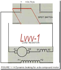
Another method of braking electric motors is known as dynamic braking. When this method is used to reduce the speed of de motors, the arma ture is connected across a load resistor when power is disconnected from the motor. If the field winding of the motor remains energized, the mo tor becomes a generator and current is supplied to the load resistor by the armature, figure 1-14. The current flowing through the armature winding cre ates a magnetic field around the armature. This magnetic field causes the armature to be attracted to the magnetic field of the pole pieces. This a tion in a de generator is known as counter torque. Using counter torque to brake a de motor is known as dynamic braking.
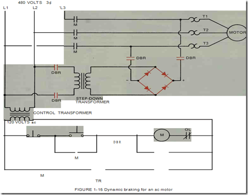
Ac induction motors can be braked by mo mentarily connecting de voltage to the stator winding, figure 1-15. When direct current is ap plied to the stator winding of an ac motor, the sta tor poles become electromagnets. Current is in duced into the windings of the rotor as the rotor continues to spin through the magnetic field. This induced current produces a magnetic field around the rotor. The magnetic field of the rotor is at tracted to the magnetic field produced in the sta tor. The attraction of these two magnetic fields produces a braking action in the motor.
An advantage of using dynamic braking is that motors can be stopped rapidly without wear ing brake linings or drums. It cannot be used to hold a suspended load, however. Mechanical brakes must be employed when a load must be held, such as with a crane or hoist.
Accurate Stops
An elevator must stop at precisely the right location so that it is aligned with the floor level. Such accurate stops are possible with the use of automatic devices interlocked with control sys tems.
Frequency of Reversals Required
Frequent n.·n·rs al s of the din:l·titlll <.lf wtation tlf tlw motor im ptl SC lar c lkmands on the l’llll trolkr nnd the ekctrktl distrihutio11 system . Spc d:tl motors and spn·ial sttrtin g nnd running pro tt’l’tive devices ma y be required to lllt’ct the t’tlnditions of frt·qul·nt I’L’Vl’t”sals . A ht·av y duty dmm switdt -nllltrn lkr is oftt:tt used I H· this pur (‘llSl’.
SPEED CONTROL OF MOTORS
Tlw spl’t’d rtlntwl is l’tlllt’l’l’lll’d not tlnly with starting tht· nwllll’ but also with maintaining or t’tlntrolling the motor spt•t•d whik it is running . Thnt· tl’l’ u munbcr llf l’tlltdititlllS to hl’ t’onsidcrt·d flll’ SJ’l’L’d l’lllltnll.
Constant Speed
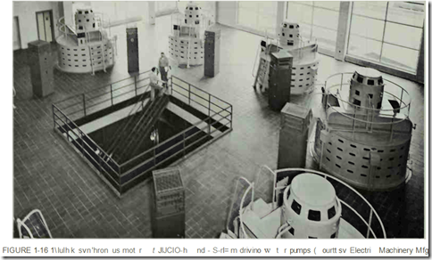
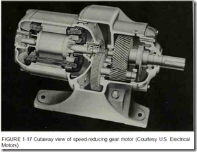
-.onstant spt·cd motors arc used on water pumps, figures 1- ll and 1- 16. 1\\ tintcawncc of constant speed is essential for motor generator sets under all lo td conditions. Constant speed motors with ratings as low as SO rpm and horsepower rat ings up to 5000 hp arc used in direct drive units. The simplest met hod of changing speeds is by gearing. Using gears, almost any “predetermined” speed nwy l)c developed by coupling the input gl·ar t<.l the shaft of a squirrel -cage induction mo tor . A speed -reducing gear motor is shown in fig ure 1- 17.
Varying Speed
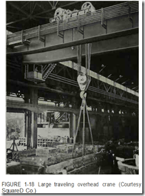
t\ varying spL·cd is usually preferred for cranes and lwists, figure 1- 18. In this type of ap plication. the motor speed slows ts the load Ill creases nnd speeds up as the load lkcreases .
Adjustable Speed
With adjustable speed controls, an operator can gradually adjust the speed of a motor over a wide range while the motor is running. The speed may be preset, but once it is adjusted it remains essentially constant at any load within the rating of the motor.
Multispeed
For multispeed motors, such as the type used on turret lathes in a machine shop, the speed can be set at two or more definite rates. Once the mo tor is set at a definite speed, the speed will remain practically constant regardless of load changes.
PROTECTIVE FEATURES
The particular application of each motor and control installation must be considered to deter mine what protective features are required to be installed and maintained.
Overload Protection
Running protection and overload protection refer to the same thing. This protection may be an integral part of the motor or be separate. A con troller with electrical overload protection will pro tect a motor from burning up while allowing the motor to achieve its maximum available power un der a range of overload and temperature condi tions. An electrical ovedoad on the motor may be caused by mechanical overload on driven ma chinery, a low line voltage, an open electrical line in a polyphase system resulting in single-phase op eration, motor problems such as too badly worn bearings, loose terminal connections, or poor ven tilation within the motor.
Open Field Protection
De shunt and compound-wound motors can be protected against the loss of field excitation by field loss relays. Other protective arrangements are used with starting equipment for de and ac syn chronous motors. Some sizes of de motors may race dangerously with the loss of field excitation while other motors may not race due to friction and the fact that they are small.
Open-Phase Protection
Phase failure in a three-phase circuit may be caused by a blown fuse, an open connection, a broken line or other reasons. If phase failure oc curs when the motor is at a standstill during at tempts to start, the stator currents will rise to a very high value and will remain there, but the mo tor will remain stationary (not turn). Since the windings are not properly ventilated while the mo tor is stationary, the heating produced by the high currents may damage them. Dangerous conditions also are possible while the motor is running. When the motor is running and an open-phase condition occurs, the motor may continue to run. The torque will decrease, possibly to the point of motor “stall”; this condition is called breakdown torque.
Reversed Phase Protection
If two phases of the supply of a three-phase induction motor are interchanged (phase reversal), the motor will reverse its direction of rotation. In elevator operation and industrial applications, this reversal can result in serious damage. Phase failure and phase reversal relays are safety devices used to protect motors, machines, and personnel from the hazards of open-phase or reversed-phase condi tions.
Overtravel Protection
Control devices are used in magnetic starter circuits to govern the starting, stopping, and re versal of electric motors. These devices can be used to control regular machine operation or they can be used as safety emergency switches to pre vent the improper functioning of machinery.
Overspeed Protection
Excessive motor speeds can damage a driven machine, materials in the industrial process, or the motor. Overspeed safety protection is provided in control equipment for paper and printing plants, steel mills, processing plants, and the textile in dustry.
Reversed Current Protection
Accidental reversal of currents in direct-cur rent controllers can have serious effects. Direct current controllers used with three-phase alternat ing-current systems that experience phase failures and phase reversals are also subject to damage. Reverse current protection is an important provi sion for battery charging and electroplating equip ment.
Mechanical Protection
An enclosure may increase the life span and contribute to the trouble-free operation of a motor and controller. Enclosures with particular ratings
such as general purpose, watertight, dustproof, explosionproof, and corrosion resistant are used for specific applications, figure 1-19. All enclo sures must meet the requirements of national and local electrical codes and building codes.
Short Circuit Protection
For large motors with greater than fractional horsepower ratings, short circuit and ground fault protection generally is installed in the same enclo sure as the motor-disconnecting means. Overcur rent devices (such as fuses and circuit breakers) are used to protect the motor branch circuit con ductors, the motor control apparatus, and the mo tor itself against sustained overcurrent due to short circuits and grounds, and prolonged and ex cessive starting currents.
CLASSIFICATION OF AUTOMATIC MOTOR STARTING CONTROL SYSTEMS
The numerous types of automatic starting and control systems are grouped into the following classifications: current limiting acceleration and time delay acceleration.
Current Limiting Acceleration
This is also called compensating time. It refers to the amount of current or voltage drop required to open and close magnetic switches when used in a motor accelerating controller. The rise and fall of the current or voltage determines a timing pe riod which is used mainly for de motor control. Examples of types of current limiting acceleration are:
• Counter emf or voltage drop acceleration
• Lockout contactor or series relay acceleration
Time Delay Acceleration
For this classification, definite time relays are used to obtain a preset timing period. Once the period is preset, it does not vary regardless of cur rent or voltage changes occurring during motor ac celeration. The following timers and timing sys tems are used for motor acceleration; some are also used in interlocking circuits for automatic control systems.
• Pneumatic timing
• Motor-driven timers
• Capacitor timing
• Electronic timers
• Dashpot timers
TROUBLESHOOTING
One of the primary jobs of an industrial elec trician is troubleshooting control circuits. An elec trician that is proficient in troubleshooting is sought after by most of industry. The greatest troubleshooting tool an electrician can possess is the ability to read and understand control sche matic diagrams. Many of the circuits shown in this text are accompanied by detailed explanations of the operation of the circuit. If the circuit and ex planation are studied step by step, the student will have an excellent understanding of control sche matics when this text is completed.
Most electricians follow a set procedure when troubleshooting a circuit. If the problem has occurred several times in the past and was caused by the same component each time, most electricians check that component first. If that component proves to be the problem, much time has been saved by not having to trace the entire circuit.
Another method of troubleshooting a circuit
is shot gun troubleshooting. This method derives its name from the manner in which components are tested. Instead of following the circuit in a log ical step-by-step procedure, the electrician quickly checks the major components of the circuit. This approach is used to save time because in many in dustrial situations an inoperative piece of equip ment can cost a company thousands of dollars for each hour it is not working.
When neither of these methods reveals the
problem, the electrician must use the control sche matic to trace the circuit in a logical step-by-step procedure. The primary tool used to trace a circuit is the volt-ohm-milliammeter (VOM), which mea sures voltage, current, and resistance. It is often necessary to use jumper leads to bridge open con tacts when using the VOM. When a jumper lead is used for this application, it should be provided with short circuit protection. This can be done by connecting a small fuse holder or circuit breaker in series with the jumper lead. In this way if the jumper is accidently shorted, the fuse or circuit breaker will open and protect the rest of the cir cuit.
When troubleshooting a circuit, most electri cians work backward through the circuit. For ex ample, one line of a control schematic is shown in figure 1-20. M relay coil is connected in series with a normally closed overload contact, a normally open limit switch contact, a normally closed pres sure switch contact, a normally closed CR relay contact, and a normally open float switch contact. The problem with the circuit is that M relay coil will not energize. The first test should be to mea sure the voltage’ at each end of the circuit to con firm the presence of control voltage. The next pro cedure is to connect the voltmeter across each of the circuit components to determine which one is open and stopping the current flow to the coil. When the voltmeter is connected across a closed contact, there is no voltage drop, and the meter indicates 0 volts. If the voltmeter is connected across an open contact, the meter indicates the full voltage of the circuit.
Assume in this circuit that the full circuit voltage is indicated when the meter is connected across float switch FS. This reading signals that float switch FS is open. The next step is to deter mine if the switch is bad or if the liquid lever it is sensing has not risen high enough to close the switch. Once that has been determined, the elec trician can correct the problem.
