Special ac motors and their applications inindus ry
Here arefO’Ur types of ac motors not often seen in industrial plants. Why are they different? What are their operating principles and means of control?
What applications do they have?
By ALFRED BERUTII Associate Editor
SUBMERSIBLE oil-pump motors, LIMs, PAMs and step motors all represent takeoffs in technology from the standard ac induction motors found in all commercial and industrial loca tions. Each was developed to answer a particular need not satisfied by the normal T-frame or U-frame induction motor. The theory of their operation, how they are controlled, and the tasks to which they have been applied may suggest new industrial and commercial uses.
Linear motors (LIM)
A linear induction motor differs from the squirrel-cage induction motor in that it converts electrical energy into linear rather than rotational motion. LIMs are at work in things like door operators, power staplers, foil feeders, transportation vehicles, and process equipment mechanisms. Still, they remain as comparatively unknown items when contrasted with their rotary cousins.
A quick review of basic ac squirrel cage motor principles is in order. Current flowing in the stator windings magnetizes the stator iron and creates magnetic poles. The magnetic flux from north to south pole completes its circuit through the air gap and rotor iron. This magnetic field is made to rotate by varying the amount and direction of current flow in the stator coils. Faraday discovered that when a conductor forming part of a closed circuit is moved through a magnetic field, current flows in the conductor. The rotating field cutting through the squirrel-cage bars thus causes an induced current. The magnetic field set up by the current flow in the rotor also establishes north and south poles. The north pole of one field attempts to line up with the south pole of the other field. Since the stator magnetic field is rotating, the rotor field attempts to follow and thereby turns the rotor. When their alignment is prevented by the need to furnish torque to a shaft load, energy conversion takes place. The torque produced is proportional to the angle between the fields. In the squirrel-cage induction motor, slip be tween stator rotating field speed and the rotor speed provides the means by which lines of force are continually cutting across the squirrel-cage bars, generating voltages in them.
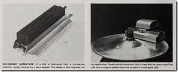
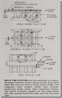
In the linear motor, the stator and its coils are split along its axis and unrolled flat. The magnetic field, instead of rotating, simply sweeps along the length of the stator (termed the “primary” or “motor” in a LIM). The equivalent of the rotor in a LIM is the “secondary” or “armature.” The secon9ary is a conductive material, either copper or aluminum, most often shaped to suit the requirement of the application. As such it can be a rail, a rod, a disc, a sheet of foil, etc. Curr en ts induced in the secondary set up a magnetic field. The interaction of the two magnetic field s produc es t h e required linear force. It is well to note that in the squirrel-cage in du ction motor, the torque generated acts upon the rotor and stator equally. The torque on the stator is transmi tted through the frame of th e machin e to the foundation and therefore only th e rotor turns. In the LIM, it can be either element that is free to move while the other is held in place . This factor increases the flexibility of application of the LIM.
Types of L!Ms –There are th ree basic configurations of LIM s-open face flat LIM, double-sided flat LIM, and rod-style LIM. The open-face flat LIM follows the configuration descrip tion given above. Usually, a magn etic keeper (backing sheet) is provided as part of the secondary condu ctor. This acts to provide structural rigidity ; but more importantly, it provides a return path for the magnetic flux of the primary. Without the keeper, the heat generated is greater and the power factor of the LIM is lower.
The double-sided flat LiM is simply two open -faced flat LIMs placed oppo site each oth er. One advantage gained by this arrangement is that the iron of th e opposed coils acts as the path for th e flux, thereby eliminating the need for a magnetic keeper for the second ary.
Take an open-faced flat LIM, roll it up along its length into a cylinder, and you have a rod-type LIM. A soft-steel, copper -coated tube serves as the sec ondary.Characteristics and control-Clear ance is the key factor to LIM motor perf ormance. The smaller the gap, the greater the efficiency. It is inherently easier to maintain a small uniform gap in an open -faced flat LIM rather than between two opposing faces and the secondary, or between a round rod and the surrounding coils. So, the open faced flat LIM is not only the simplest; it is also th e most efficient.
LIMs are electrically reversible.
Th ey provide power in either direction. Be reversing the motor, a braking force can be applied.
As with any electromagnetic device, the limitations of a LIM are set by the amount of heat it generates and the ability it has to dissipate that heat. The iron that separates the coils of the primary also act to dissipate heat; however, in certain applications, addi tional heat-sinking or auxiliary cooling means are necessary. Another ap proach for minimizing heat generation is simply by turning off power whenev er possible-at the end of a stroke, when coasting, etc. By so doing, the duty cycle of the LIM can be reduced.
Velocity of a LIM is determined by the balance between linear force applied and load characteristics. The LIM acceler ated quickly in an attempt to reach its theoretical synchronous speed (160 ips for 3-phase units). Under load, it may reach a speed as high as 90 ips. For many applications, thi s speed is too high and some form of speed control is necessary. The recom mended method of speed control is by usi ng a velocity feedback signal to modulate the power to the motor. A rotary tachometer is used as the feed back source for low-speed applications, while an eddy-current device is used
for higher-speed applications. The sig nal is used to control the firing angle of an SCR, thus setting the rms voltage to the motor. Since the linear force produced is proportional to power and the square of the applied voltage, force control is achieved, and the LIM main tains constant velocity .
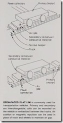
Applications –Possibly the most glamorous use of the open-faced flat LIM is as the prime mover for trans portation vehicles. Here, the inter changeabilit y of function of the prima ry and secondary are most easily visualized. The prima ry coils can be embedded between tracks. Coil spacing allows the vehicle to coast from one coil to the next. Or, th e coils can be mounted on the vehicle and the track or path can be a conductive material backed by ferrous material. The gap between primary and secondary need not depend upon wheels on a rail. An air cushion or magnetic repulsion system would function ju st as effec tively.
Disney World in Orlando, Fla. con tains several examples of the use of LIM s for transportation. The Space Mountain ‘s vehicles, as well as people movers elsewhere in the park, are propelled by LIMs. In these installa tions, the primary coils are laid between the rails. The plastic-encapsu lated coils are 10 in. wide by 15 in. long and 21/z in. thick.
The double-sided flat LIM is most often seen in industrial and commer cial locations as door operators. Here the primary is stationary, while the door is attached to the rail-shaped secondary. Gear reducers, clutches and other mechanical devices are elimi nated entirely. Since speed can be controlled in both directions separate ly, the speed of opening and the speed of closing can be set to different values.
Another application for this type of .LIM is in foil feeders. The foil, usually aluminum, acts as the secondary. In a typical application, the foil is fed into presses, where it is formed into pie plates, etc.
Rod-style LIMs can be used in any application where a shaft must com plete a stroke to move or restrain an object. Strokes up to 10 or 12 ft are possible. Either the rod can be free to act as the prime mover, or the load can be attached to the motor. Rod-style LIMs have been used to feed stock into presses, to provide lifting motion on conveyor transfer applications, as shock absorbing stops (by opposing the weight of traveling objects with a set force), and in place of solenoids for applications requiring motion over 1/2 in .
A further extension of the rod-style LIM technology has resulted in a step rod LIM. In these units, the controller pulses the rod-style LIM. Exact rod positioning can be achieved.
Pole amplitude modulation motors (PAM)
There are several ways to achieve variable flow rates for fans and pumps. The inlet to the system can be throt tled, the outlet from the system can be throttled, or the speed may be controlled. By throttling, the output is reduced by the additional pressure drop through the device used to vary the rate. In speed control, both flow and pressure are reduced as a function of driver speed.
Of the methods available for varying flow, the most efficient is speed control. For example: if flow were to be reduced from 100% to 30% of normal, outlet throttling would require 50% of rated power input by the motor. If inlet control was used, the input power requirement would drop to 30%. Wi h speed control, the input power require ment would drop to only 3%.
While speed control points out a potential for energy savings, it is not always economically viable. But when flow range is wide, or when the drive must operate for long intervals at low flow conditions, speed control should be investigated.
There are several ways to achieve speed control when an ac motor is used as the prime mover. It can be done with a motor having two separate windings, with a consequent pole motor having a single 2:1 ratio winding, with a single-speed squirrel-cage induction motor equipped with an intermediate speed adjusting device, with a variable frequency drive, or with a PAM motor.
Construction-PAM motors are two-speed, single-winding motors. However, they are not limited to the standard 2:1 speed ratios. Ratios can be as high as 10:2 or as close as 6:8.
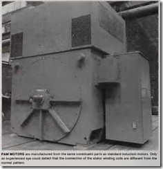
PAMs are manufactured as standard induction motors. Only an experienced eye could detect that the connection of the stator winding coils varies from that of the single-speed motor. Six leads , are brought out to the motor junction box.
Theory of operation- The speed of any motor is determined by:
A 4-pole machine will thus have a speed of 1800 rpm at a frequency of 60 Hz. If the windings can be switched so that electrically the number of effec tive poles can be changed, then speed will also change.
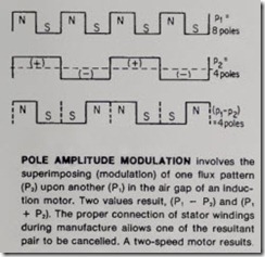
As with the ordinary consequent pole motor, the windings of the PAM are connected in series at one speed and in parallel at the other. However, by building the motor with the stator coils connected properly, the flux pattern of a group of poles can be superimposed on the original flux pattern. The result is modulation that
effectively cancels the magnetic effect of some poles, varying the speed.
An analogy to modulation in a PAM is to consider the method used to trans mit AM radio signals. The frequency of the spoken word (P1) is superimposed over (modulates ) a second higher
carrier frequency (P2). Two additional frequencies are produced; (P1 – P2) and (P1 +P2). Both are high frequencies and can therefore be transmitted over long distances. The modulated carrier fre quency is transmitted, and in the receiver the (P2) signal is filtered out. Only the voice frequencies remain. It is the (P1– P2) and (P1 + P2) values that are produced by superimposing flux patterns in the PAM that is used to achieve the second speed. The connec tion pattern of the windings allow either (P1 – P2) or (P1 + P2) to be eliminated, thus achieving two speeds at any ratios desired.
Starting and switching-Starting and switching can be accomplished using a standard starter plus a 5-pole auxiliary contactor. More often it is performed by using a starter in combi nation with a motorized switch. When changing speeds, the motor is momen tarily deenergized by opening the starter. After a short delay the trans fer of switch position is made, and the starter is energized.
Applications- It is common practice to run forced-draft and induced-draftfans at less than their maximum capacity for extended periods. Two speed motors allow for such cyclic operation as well as the case where provisions must be made for future capacity.
Retrofitting of existing equipment to achieve maximum energy efficiency is an increasingly important considera tion. By matching the need to the speed as closely as possible, energ-s can be saved.
For those applications where lower than-normal motor inrush current is required, PAMs can be used. By start ing on the low-speed winding and then transfering to the high-speed winding, a reduction in inrush can be accom plished. This offers an alternative to reduced voltage starting methods.
PAMs are also available as 2-wind ing, 4-speed motors and in all three categories of multispeed application variable torque, constant torque, and constant horsepower.
Step motors
A step motor is an electromagnetic device that converts digital electrical signals into fixed mechanical move ment. Conventional motors rotate con tinuously when energized. A step motor rotates in fixed angular incre ments each time it is energized. The step angle is fixed and is determined by the construction of the motor. Com monly available step motors range from step angles of 0.72 degrees (500 steps per revolution) to 45 degrees (8steps per revolution).
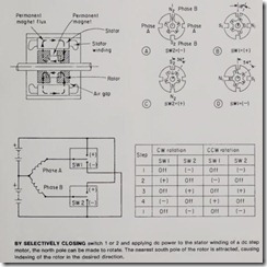
How they work-In the majority of applications of step motors, a permanent-magnet type motor is used. In a simplified form, this motor is made up of a stator with teeth that are magne tized to form north and south poles when de power is applied to the appropriate stator windings, and a two-part rotor separated by a permanent mag net. The rotor is also toothed; but the south teeth are offset from the north set so that when a rotor S is attracted to a stator N, there is a rotor N that is simultaneously attracted to a stator S. By selectively applying de voltage to the stator windings, the stator N and S poles can be caused to rotate. The rotor will step until the closest N and S of the rotor line up with the S and N of the stator. The discrete steps are achieved by having an unequal number of teeth in the stator and the rotor. For example, if there are four stator poles, then there would be five rotor teeth. Therefore, only one set of teeth can line up at one time. The exact number of teeth determines the step angle.
The control of a step motor involves sequential switching of de power to the stator windings. Depending upon the controller used to supply the pulses, stepping rates of 10,000 full steps (or 20,000 half steps) per second can be achieved. Typically, the controller would interface with a digital control ler or computer for precise positioning of machine-tool components.
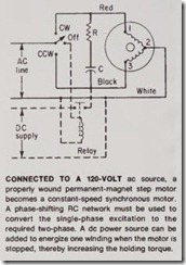
At this point, the question may arise, “What is a discussion of de step motors doing in an article on ac motors?” The answer is that the permanent magnet de step motor was originally developed as a slow-speed synchronous inductor motor! An appropriately wound de permanent-magnet motor, connected to a single-phase, 120-volt, ac supply, can be operated as an ac synchronous, constant-speed motor. All that is necessary to be added is an RC network for phase shifting (not required if oper ated from 2-phase source), and a 3-position switch to provide FORWARD OFF-REVERSE control. Virtually instan taneous starting and stopping charac teristics make the ac version ideal for precise motion control. Generally, the motor will start within 1112 cycles and stop within 5 mechanical degrees. Full synchronous speed is reached within 5 to 25 milliseconds. No braking system is required to achieve the small stop ping distance; simply de-energize the motor.
Current flows through the stator windings only when the motor is ener gized. No current flows through the rotor. Thus, ac starting and running currents are virtually identical-there are no high inrush currents.
The torque output of the motor is proportional to the applied voltage, and the speed of the motor is directly proportional to the applied frequency. Therefore, within limits, both torque and speed are adjustable.
Once the motor has been deener gized, residual holding torque is sup plied by the permanent-magnet rotor. If more holding torque is required, de power can be applied to one or both of the stator windings. Holding torque of the two windings will be increased by 120% and 150% above the rated resid ual torque of the motor.
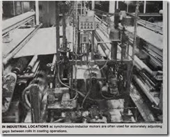
Applications- The ac synchronous version of the de step motor is most often found in industrial environments, applied where precise motion control is necessary. Gaps of coating rolls in high-speed treating lines must fre quently be adjusted to apply precise thicknesses of finish to materials. The permanent-magnet synchronous motor has been used to change and maintain these gaps. They are also seen in edge guide controls and as remote controls for switches and rheostats.
Submersible oil-well pump motors
We often think of oil wells in terms of pictures we have seen of great torrents of oil spewing from the ground when a well has been brought in. The gusher covers drilling rig, crew, and landscape with “black gold” until it is capped off. Actually, subsurface pres sure most often is not sufficient to keep oil flowing to the surface of a produc ing well. One of the means used to achieve artificial lift is with an electri cal centrifugal subsurface (downhole) pumping system.
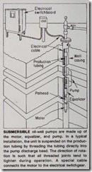
How can a pump and its motor be lowered thousands of feet into a well when the casing of the well has an outsid e diameter of only 5112 in., 7 in., or 8% in.? The answer is by making the entire motor-pump assembly only 44fs in. in diameter-for a 51fz-in . OD pipe-and up to 120 ft long! Obviously, this is not the standard NEMA frame size, squirrel-cage indu ction motor that we are dealing with.
Motor design-Motors used in sub mersible oil-well pump service are usually 3-phase, 3500-rpm induction motors . Ratings range up to 275 hp for 5112-in. OD casings, and up to 550 hp for 8%-in. OD casing wells. The motors are oil-filled and are cooled by the transfer of h eat to the. well fluid moving past the motor and into the pump. The pump is located above the motor in the typical configuration.
Temperature is an important factor at the depths at which submersible oil-well pumps are used. The farther down, the higher the temperature . Thus, while the ambient temperature is considered to be 40C for the stan dard application of a squirrel-cage induction motor, submersible oil-well pump motors are rated to carry full load at ambients of 120C. Also, insula tion systems have been developed that exceed the total allowable temperature for Class H insulation.
The motor itself can be up to 30 ft in length for a 275-hp motor used in a 51fz-in. pipe application . Of this length, approximately 29 ft are used up for the stator iron. Bearings are inserted approximately every 14 in. within the stator to support the rotor. A built-in oil filter continuously cleans and filters the motor oil to insure a constant supply of clean oil to the bearings. Otherwise, the rotor and stator are both of standard squirrel-cage con struction.
Motor leads are brought out through a pothead fitting. This insures good sealing around the cable and prevents contamination of the motor oil by the well fluid. As an additional safeguard against introduction of well fluid into the motor, a unit called an equalizer is mounted between the motor and the pump. The equalizer serves as a barrier to the migration of fluid along the shaft connecting the pump and motor. It also allows for free expansion and contraction of the motor oil without danger of contamination .
Electrical distribution system- If the configuration of the submersible oil-well pump motor seems unusual, then consider the voltage ratings. The standard voltages for these pump motors are 440 and 762 volts. Higher voltages up to 2300 volts are also avail able.
For a given wire size and voltage drop, a load can be located three times as far away when fed at 762 volts than if it were fed at 440 volts. In applica tions where downhole distances run into thousands of feet, the advantage of the higher voltage level is obvious. The rule-of-thumb used to set depth limits is: do not consider a 762-volt motor if the horsepower x the depth exceeds 200,000. For greater depths, higher voltages should be used.
Why was a voltage level of 762 volts made a standard for submersible oil well pump motors? Because there are several convenient ways of obtaining this voltage at an installation that already operates on 440 volts. The first is by the use of autotransformers connected to the existing 440-volt system. The second is to use three single-phase, standard, 440-volt trans formers. By connecting their secondar ies in wye, 762 volts is obtained phase to-phase.
Specially designed 3-kv cable is normally used from starting equip ment to motor. The cable can be fiat or round, armored or unarmored. The ampacity of the cable varies from NE Code values because of the unusual thermal environment in which it must operate. The maximum ampere limits are somewhat flexible, since the tem perature of wells can vary considera bly. A “cold well” may run from 75F to 125F. “Hot wells” may exceed 250F.
Voltage drop is an important consid eration in the selection of the cable size. With the distances experienced in a typical well application, volt age drop is often the limiting factor. By oversiz ing a cable, voltage drop can be reduced . However, space limitations in the well casing limit this option . The next alternative is to boost the surface input voltage. This is most often accomplished by taking advantage of the transformer taps. In a 762-volt system, the two 21/z % taps allow the voltage to be boosted to 800 volts.
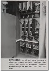
Start ing equipment and controls Switchboards are used to house the starting equipment , monitoring de vices, and control equipment. General ly they are NEMA 3 weatherproof. The starters used are those that are normally used for across-the-line start ing of the standard squirrel-cage induction motor. This includes a dis connect device, contactor, overload re lay, and 4401110-volt control trans former. Recording ammeter, undercur rent shutdown relaying, and lightning arresters are also usually mounted in the enclosure.
What sets submersible oil-well pump switchboards apart from the starting equipment found in most comm ercial and industrial sites are the voltage ratings . The standard ratings are 440 volts, 880 volts, 1500 volts, and 2500 volts . These voltages represent the maximum voltages that are likely to be encountered on the var ious voltage distribution systems.
Application s- Besides service as submersible pumps in oil wells, these pumps have been used in a variety of different applications. They are u sed on off-shore drilling rigs as sump pumps, fresh-water supply pumps, cooling-system pumps, fire-protection pumps, and crude-oil transfer pumps . They find application as storage cavern and mine-shaft evacuation pumps. Submersible oil well pumps can also act sirimltaneously as a production and injecting pump. By providing lift while injecting the fluid into a reser voir at required presures, surface injec tion pumps and structures can be elim inated.
