Motor burnout on single-phasing
Loss of three 100-hp motors in an industrial plant emphasizes that properly set conventional running-overload protection in controllers for 3-phase motors is no assurance of protection against costly motor burnouts on “single-phasing” of the supply circuit.
N A MODERN, well-designed and effectively maintained electrical system in an industrial plant, a recent case of costly motor damage due to “single phasing” of the supply system under scores a painful reality of the electrical industry-namely, that constantly growing motor applications in all kinds of electrical systems all over the nation is being paced by a constantly growing experience with motor burnouts due to “single-phasing.”
Although the National Electrical Code requires protection for motors against running overloads, there is no mention at all in the NEC of any need for protection against single-phasing damage-the damage that can be pro duced in 3-phase motors when one of the three phase legs of the motor cir cuit loses voltage due to blowing of one of the three fuses protecting either the branch circuit to the motor or the feed er or service supplying the branch cir cuit. Three running-overload relays in the motor starter can protect against motor damage by opening the starter under certain conditions of single phasing, but the hard truth is that three overload relays constitute only partial protection under very specific conditions of motor loading and appli cation.
Complete and effective protection against the threat of single-phasing damage is an extremely important task for the motor-circuit designer. Some motor controller manufacturers incorporate antisingle-phasing in their equipment (in particular, the European designs), but the majority of 3-phase motor starters do not include such protection. As described in the following case study of single-phasing burnout, existing starters can be retrofitted with the necessary electrical compo nents to provide such protection although such an addition, as in the case here, may be a case of locking the barn door after the horses have been stolen.
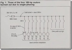
As shown in Fig. 1, the single-phas ing damage in the industrial plant involved three of four 100-hp motors driving ammonia compressors. One 100-hp motor and three other smaller compressor motors were subjected to the same single-phasing as the burned out motors, but the running overload relays in their starters opened the starters and saved the motors from damage. The single-phasing occurred as a result of blowing of one of the three 3000-A silver-sand current-limit ing fuses in the main service disconnect of the plant’s main switchboard. A very important factor in this incident is that the single-phasing occurred during a utility brownout (reduced voltage) late in the afternoon of a hot summer day.
The following are excerpts from the engineering department’s report on the incident:
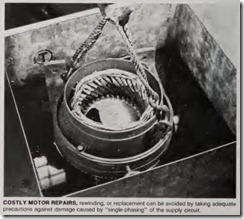
At 5:02 p.m. one of the main fuses in our main service disconnect blew, caus ing single-phasing of the system, which resulted in the ultimate loss of three 100-hp motors. Two were total burnouts requiring replaceme nt, and one was severely damaged but capable of being rewound. When the smgle-phasing oc curred, plant personne l were immediate ly alerted to a problem because of imme diate loss of lighting fed by the opened phase. Within 30 minutes, smoke was noticed at the motors, which continued to “cook” until they burned their supply open. Neither the motor starters nor the branch circuit breakers operated to clear the faults.
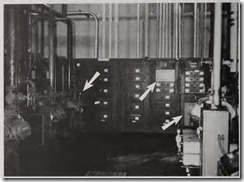
FIG. 2. Ma in switchboard conta ins the 3000-A fused main service disconnect switch (left arrow) and the 400-A CBs for the 100-hp compressor motors as well as the branch-circu it CBs (right arrows) for other equipment, including the smal ler compres sors at left (90, 75 and 40 hp).
Two of the motors (one burned-out, one damaged) were driving ammonia compressors for process line No. 1; the other burned-out motor was driving an ammonia compressor for process line No. 2. At that time, line No. 2 was already operating on its second shift, and line No. 1 was preparing to com mence running. We believe all compres sors for line No. 1 were turned on but operated unloaded. The same was true of the damaged motor on line No.2.
When the singl e-phasing occurred by blowing of one of the main 3000-A fuses, the maximum service current draw was probably not over 2000 A- in service fuses that are rated at 3000 A. The pow er company’s pole-line protection did not trip, and there is no other indication of any other overload th?-t would cause the one fuse to go, although there was a brief high-voltage transient (microsec onds in duration) passing through our switchboard from the utility lines. The main fuses in the switchboard main were originals dating back to 1967, and the blown fuse may have metal-fatigued and crystallized due to high-heat cycling over the many years of operation Because compressor motors, in partic ular, run in both full-load and unloaded conditions, they are extremely vulnera ble to burn-out if they single-phase while in an unloaded condition. Anti single-phasing protection is being added to all of the compressor starters. This is a protector that will drop a motor out if one of its phases loses current flow. There is nothing that could have been done to protect against this failure other than to have put these phase protectors in earlier.
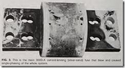
Fig. 2 shows the main service switchboard that contained the 3000-A main fuse that blew (in main discon nect section at left arrow). The 400-A CBs providing motor branch-circuit protection for the 100-hp motors are shown (right arrows) in the board and were not actuated by the single-phase fault condition. Fig. 3 shows the main 300-A fuse that blew and caused the single-phasing. It was hypothesized that one or more of its internal links has opened over the years, derating the fuse continuous-current value to some thing less than 3000 A. In such a condi tion, the fuse would be susceptible to blow on an inrush current that it was exposed to while preheated to a high temperature by the fairly constant demand load current of around 2000 A. Discoloration of the fuse blades indi cated poor contact between the bolted blades and the fuseholders in the main switch, which could have made a sig nificant contribution to fuse overheat ing and utlimate blowing.
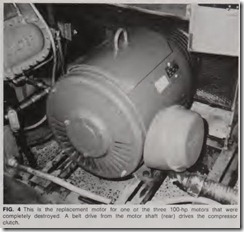
Fig. 4 shows one of the replaced 100-hp motors, which is controlled by the part-winding starter shown in Fig.5. After the single-phasing damage to the motors, the starter for each com pressor motor was equipped with anti single-phasing protection, as shown in Fig. 5 and the close-up of Fig 6. The current transformers and the relay shown at left provide for opening the starter on failure (opening) of any one of the three phases. Such a relay hook up can also protect against unbalance in phase currents, such as might occur due to a partial winding short or a ground fault in a motor winding. Sens ing such fault early and opening the starter can reduce the extent of dam· age to a motor.
Single-phasing action
Fig. 7 shows the typical characteris tics of a squirrel-cage induction motor as related to a 100-hp unit. At no-load (or light-load), both efficiency and power factor are drastically redu ced from their full-load values, and that can account for very high n o-load motor currents du ri ng single-phase graph are applied to analysis of the basic concepts behind single-phasing of a 3-phase motor.
Analyzed by symmetrical compo nents, a single-phasing condition in volves two balanced polyphase systems of opposite phase sequency-produci ng a positive and negative torque with the resultant effective torque being the dif ference between the two. Depend ing upon the type of motor windi ng (star or delta-connected), some amount of harmonic current is generated in the windings and contributes to exaggerated heating effects within the wind ings under single-phasing conditions.
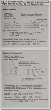
Fig. 8 presents a simplified compari son between normal 3-phase operation of a fully loaded 100-hp motor and single-phase fault operation of the same motor fully loaded. The analysis in the general nature of each type of operation. The num erical values are selected as typical and representative of the changing actions from normal to single-phase operation. Change in pow er factor and efficiency accompany the change in operating conditions as a result of shifts in the vector relation ships between currents and voltages. For practical purposes, it can generally be assumed that the single-phase cur rent under full-load conditions is about equal to 1.73 (the square-root-of-3 fac tor from 3-phase calculations) times the normal 3-phase full-load current.
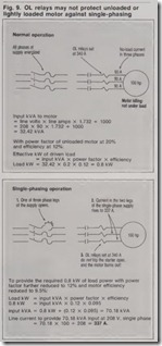
When the same 100-hp motor is operating unloaded, the line current is only 90 A, as shown for normal opera tion in Fig. 9-with the power factor and efficiency at very low value (as indicted in Fig. 7 for no-load condi tion). The effective kW rating of the load represented by the motor and clutch-the basic no-load condition-is only 0.8 kW. As shown in the bottom of Fig. 9, power factor and efficiency
change substantially under single phasing conditions-where shifts in PF and efficiency occur along the almost vertical curves for power factor and efficiency at extremely low loading (left bottom of Fig. 7). Under such conditions, it is readily possible to pro duce motor currents in excess of the full-load value of 274 A but below the actual trip setting of the OL relays. As shown, a current of 337 A could flow continuously.
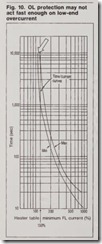
The value of 337 A is meant only to be indicative of the elevated current that might exist. In fact, if particular OL heaters happen to be actually rated at the high side of the manufacturing tolerance band for the trip current, even higher continuous current would be possible. In addition, there is always the possibility that the time-current characteristics of the heaters would permit excessive currents (above the heater pickup value) for a long enough time to damage the motor before the relay opens the starter. Fig. 10 shows the minimum-maximum operating band for one manufacturer’s overload relays, with the maximum trip curve allowing 150% of motor full-load cur rent for up to 10,000 seconds, which is over two hours and forty-five min utes-enough time to do serious dam age.
Protection against damage due to single-phasing can be facilitated by careful selection of the type and rating of running overload devices in motor starters. Whether an overload relay is a bimetallic or solder-pot thermal device or is a magnetic type of device, the shape of the inverse-time-current characteristic should conform as close ly as possible to the motor’s heat dam age curve (the time-current curve defining the limits of motor heating damage). Selection of overload relays is a more critical task than it used to be because of the wide variety of types and characteristics of both electrome chanical and solid-state relays avail able today from the broad range of manufacturers.
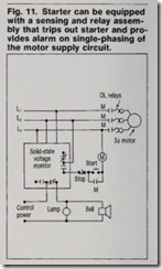
Several manufa<;_turers incorporate phase unbalance and phase failure (anti-single-phasi ng) protection in their line of motor starters. These include overload relays that trip faster and at a lower current when single phasing occurs. But anti-single-phas ing protection is more important for motors rated above 20 hp, in which sizes the differences between no-load current and full-load current are much greater than in smaller motors, there by taxing the ability of conventional 01 relays to protect against overcurrnt at any conditon of loading. For larger motor applications, the starter can be equipped with a 3-phase power monitor of the type shown in Fig. 11. In that hookup, the relay connected into the control and power circuits will drop the starter out on loss of any phase, on low voltage on any or all phases, or even phase reversal. The unit consists of a solid-state circuit hookup that senses voltage and phase angle and controls a double-pole, double-throw relay as shown.
Th e bottom line on all of this is that costly motor damage due to single phasing is today, mor e tha n ever before, a serious threat th at mu st be anticipated and eliminated.
