SERIES 90 CONTROL CIRCUITS
APPLICATION
The Series 90 low-voltage control circuit provides modulating or proportional control and can be applied to:
– Motorized valves.
– Motorized dampers.
– Sequence switching mechanisms.
The Series 90 circuit can position the controlled device (usually a motorized damper or valve) at any point between full-open and full-closed to deliver the amount of controlled variable required by the controller.
Proportional control, two-position control, and floating control have different operating limitations. For example:
1. In modulating control, when an actuator is energized, it moves the damper or valve a distance proportional to the
sensed change in the controlled variable. For example, a Series 90 thermostat with a 10-degree throttling range moves the actuator 1/10 of the total travel for each degree
change in temperature.
2. In two-position control, when an actuator is energized it moves the valve or damper to one of the extreme positions. The valve or damper position remains unchanged until conditions at the controller have moved through the entire range of the differential.
3. In floating control, when an actuator is energized, it moves the damper or valve until the controller is satisfied. The actuator maintains that position until the controller senses a need to adjust the output of the valve or damper.
Series 90 circuits combine any Series 90 controller with an actuator usable for proportioning action. Limit controls can also be added.
EQUIPMENT
CONTROLLERS
– Temperature controllers.
– Humidity controllers.
– Pressure controllers.
– Manual positioners.
Series 90 controllers differ from controllers of other series in that the electrical mechanism is a variable potentiometer rather than an electric switch. The potentiometer has a wiper that moves across a 135-ohm coil of resistance wire. Typically the wiper is positioned by the temperature, pressure, or humidity sensing element of the controller.
ACTUATORS
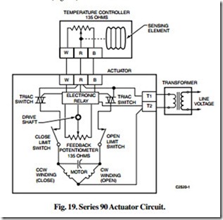
A Series 90 actuator (Fig. 19) consists of the following:
– Reversible drive motor.
– Electronic relay.
– Switching triacs.
– Feedback potentiometer.
– Gear train and drive shaft.
– Rotation limit switches.
– Optional spring-return mechanism.
The actuator has a low-voltage, reversible-drive motor which turns a drive shaft by means of a gear train. Limit switches limit drive shaft rotation to 90 or 160 degrees depending on the actuator model. The motor is started, stopped, and reversed by the electronic relay.
The feedback potentiometer is electrically identical to the one in the controller and consists of a resistance path and a movable wiper. The wiper is moved by the actuator drive shaft and can travel from one end of the resistance path to the other as the actuator drive shaft travels through its full stroke. For any given position of the actuator drive shaft, there is a corresponding position for the potentiometer wiper.
All Series 90 actuators have low-voltage motors. A line- voltage model has a built-in transformer to change the incoming line voltage to low voltage for the control circuit and the motor. Low-voltage models require an external transformer to supply the actuator (Fig. 19).
OPERATION
GENERAL
Figure 19 illustrates a basic Series 90 system including a temperature controller, actuator, and transformer. The wiper of the potentiometer on the controller is at the midpoint and the actuator drive shaft is at midposition when the controlled variable is at the setpoint. The shaft remains unchanged until the controlled variable increases or decreases. The amount the controlled variable must change to drive the actuator drive shaft from full closed to full open (or vice versa) is called the throttling range. The setpoint and the throttling range are usually adjustable at the controller.
The controller and feedback potentiometer form a bridge circuit which operates switching triacs through an electronic relay. When the controlled variable changes, the potentiometer wiper in the controller moves and unbalances the bridge circuit. The electronic relay detects the unbalance and triggers the appropriate switching triac. The triac drives the actuator drive shaft and feedback potentiometer wiper in the direction necessary to correct the unbalance. When the electronic relay detects that the bridge is rebalanced, the triac is switched off and the actuator drive shaft stops at the new position. If the actuator drive shaft drives to the full open or full closed position, the appropriate limit switch stops the motor.
For example, in a heating application a fall in temperature causes the controller potentiometer wiper R to move from W toward B. This unbalances the bridge and drives the actuator toward open. The actuator drive shaft and feedback potentiometer wiper R drives cw toward open until the bridge is rebalanced. The actuator drive shaft and feedback potentiometer then stop at a new position. On a rise in temperature, the actuator drive shaft and feedback potentiometer drive ccw toward closed stopping at a new position.
To reverse the action of the actuator, the W and B leads can be reversed at either the actuator or the controller. The actuator then drives toward the closed position as the potentiometer wiper at the controller moves toward B on a fall in the controlled variable and toward the open position as the potentiometer wiper moves toward W on a rise in the controlled variable. These connections are typically used in a cooling application.
NOTE: Most Honeywell Series 90 controllers move the potentiometer wiper toward B on a fall in the controlled variable and toward W on a rise.
BRIDGE CIRCUIT THEORY
The following sections discuss basic bridge circuit theory and limit controls as applied to Series 90 control. The drawings illustrate only the bridge circuit and electronic relay, not the triacs, motor coils, and transformer. Potentiometers are referred to as having 140 or 280 ohms for ease of calculation in the examples. These potentiometers are actually 135- or 270-ohm devices.
Basic Bridge Circuit
BRIDGE CIRCUIT IN BALANCED CONDITION
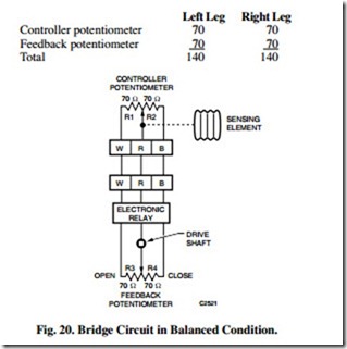
Figure 20 illustrates the bridge circuit in a balanced condition. For the bridge to be balanced, R1 plus R3 must equal R2 plus R4. R1 plus R3 is referred to as the left or W leg of the bridge, and R2 plus R4, the right or B leg of the bridge. In this example, each resistances in the left leg, R1 and R3, is 70 ohms. Together they equal 140 ohms. Similarly, each resistance in the right leg, R2 and R4, is 70 ohms. Together they also equal 140 ohms. Since the sums of the resistances in the two legs are equal, the bridge is in balance. This is shown in the following table:
When the bridge is balanced, neither triac is triggered, neither motor winding is energized, and the actuator drive shaft is stopped at a specified point in its stroke (the midposition or setpoint in this case).
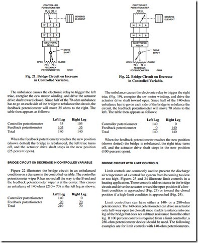
BRIDGE CIRCUIT ON INCREASE IN CONTROLLED VARIABLE
Figure 21 illustrates the bridge circuit in an unbalanced condition on an increase in the controlled variable. The controller potentiometer wiper has moved to one-fourth the distance between W and B but the feedback potentiometer wiper is at the center. This causes an unbalance of 70 ohms (175 – 105) in the right leg as follows:
BRIDGE CIRCUIT WITH LOW-LIMIT CONTROL
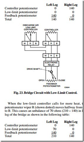
In a heating application, a low-limit controller moves a valve actuator toward open when the low-limit setting is reached. To do this, the limit controller is wired into the left or W leg of the bridge. An increase in resistance in the left leg of the controller circuit drives the actuator and feedback potentiometer toward the open position.
In Figure 23, when the controller and the low limit are satisfied (both potentiometer wipers at the W ends), the actuator is at the closed position and the bridge is balanced. This is shown in the following table:
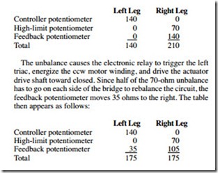
The unbalance causes the electronic relay to trigger the right triac, energize the cw motor winding, and drive the actuator drive shaft toward open. Since half of the 70-ohm unbalance has to go on each side of the bridge to rebalance the circuit, the feedback potentiometer moves 35 ohms to the left. The table then appears as follows:
When the feedback potentiometer reaches the new position (shown dotted) the bridge is rebalanced, the right triac turns off, and the actuator drive shaft stops in the new position (25 percent open).
BRIDGE CIRCUIT WITH HIGH-LIMIT CONTROL
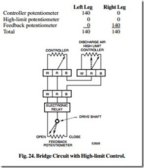
In a heating application, a high-limit controller moves a valve actuator toward closed when the high-limit setting is reached. To do this, the limit controller is wired into the right or B leg of the bridge. An increase in resistance in the right leg of the controller circuit drives the actuator and feedback potentiometer towards the closed position.
In Figure 24, when the controller and high limit are satisfied (both potentiometer wipers at the B ends), the actuator is at the open position and the bridge is balanced. This is shown in the following table:
When the high-limit controller calls for less heat, the potentiometer wiper R (shown dotted) moves halfway from B to W.
This causes an unbalance of 70 ohms (210 – 140) in the right leg of the bridge as shown in the following table:
When the feedback potentiometer reaches the new position (shown dotted) the bridge is rebalanced, the left triac turns off, and the actuator drive shaft stops in the new position (75 percent open).
CONTROL COMBINATIONS
The following illustrates common applications of Series 90 controls including low- and high-limit controls from an
application viewpoint.
LOW-LIMIT CONTROL
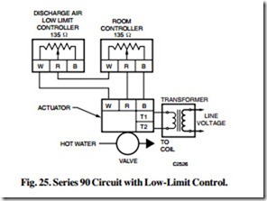
Figure 25 illustrates a typical Series 90 circuit for a heating application with a room controller, motorized valve, and a lowlimit controller located in the discharge air to the space. The temperature of the space can rise rapidly as a result of increased solar radiation, occupancy, or other conditions resulting in a sudden decrease in heating load. The room controller is then satisfied and closes the valve to the heating coil. If the system uses outdoor air, closing the valve to the heating coil can cause air to be discharged into the room at a temperature lower than desirable. To correct this, the low-limit controller causes the valve to move toward open thus limiting the low temperature of the discharge air.
HIGH-LIMIT CONTROL
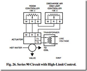
Figure 26 illustrates a typical Series 90 circuit for a heating application with a room controller, motorized valve, and high- limit controller located in the discharge air to the space. This circuit is used when there is danger of the temperature rising too high. The high-limit controller takes over control of the valve to the heating coil if the discharge air temperature rises above a comfortable level. This circuit is similar to the low- limit circuit except that the high-limit controller is in the B leg of the actuator circuit and drives the actuator toward the closed position.
TWO-POSITION LIMIT CONTROL
Two-position limit controllers can be used in Series 90 circuits where proportioning action is unnecessary or undesirable. They must be snap-acting, spdt. Two-position controls should not be used where the temperature of the the controller and shorts R to W at the actuator. The actuator drives to the closed position. Such a hookup is often used in fan heating systems to manually close a valve or damper when operation is unnecessary.
controlled variable is greatly affected by the opening and closing of the controlled valve or damper. For example, if Series 60 high- or low-limit controllers are used as limit controllers in discharge air, whenever the temperature of the air is within the range of the limit controller, the steam valve for the heating coil will cycle on and off continuously.
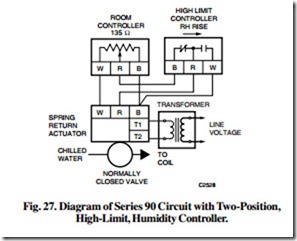
Figure 27 illustrates a Series 90 circuit with a temperature controller, normally closed (spring-return actuator) cooling valve, and a two-position, high-limit humidity controller. When the humidity is below the setting of the high-limit humidity controller, the R circuit is completed from the Series 90 controller to the actuator and the cooling valve is controlled normally. If the humidity rises above the setting of the limit controller, R to B is connected at the actuator and the cooling valve opens fully. Reheat is advisable in a system of this kind since opening the cooling valve to reduce humidity also lowers the temperature of the air and may result in occupant discomfort.
MANUAL AND AUTOMATIC SWITCHING
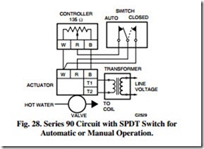
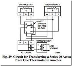
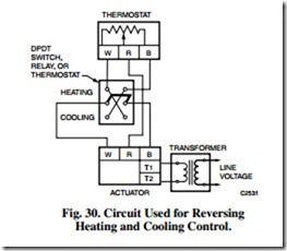
Figures 28 through 31 illustrate various uses of manual switches or relays in Series 90 circuits. Substitute a relay with the same switching action as a manual switch where automatic switching is desired.
Closing the Actuator with a Manual Switch
Figure 28 shows a manual switch with spdt switching action. With the switch in auto position, the R circuit is completed from the controller to the actuator. The actuator operates normally under control of the controller. Placing the switch in the closed position (dotted arrow) opens the R circuit from the controller and shorts R to W at the actuator. The actuator drives to the closed position. Such a hookup is often used in fan heating systems to manually close a valve or damper when operation is unnecessary.
Transferring Actuator Control from One Thermostat to Another
Figure 29 illustrates using a dpdt switch or time clock to transfer control of a single Series 90 actuator from one thermostat to another. Opening both the W and B wires prevents interaction of the two thermostats when taking one of them out of control. The R wire need not be opened.
Reversing for Heating and Cooling Control
Figure 30 shows a thermostat used for both heating and cooling control. With the switch in the heating position, the thermostat and actuator are wired B to B and W to W. With the switch in the cooling position they are wired B to W and W to B which causes the actuator to operate the opposite of heating control.
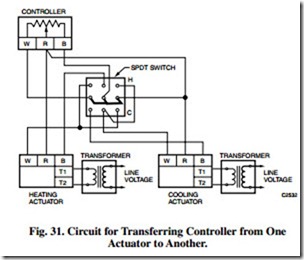
Transferring Controller from One Actuator to Another
Figure 31 illustrates a circuit which allows a single controller to control two Series 90 actuators, one at a time. With the 3pdt switch in the Cooling (C) position, the circuit connects the controller to the cooling actuator with B to W and W to B. The cooling actuator operates under normal control of the controller. At the same time, the manual switch causes R to W to connect at the heating actuator, positively closing it. With the switch in the Heating (H) position, the controller is connected B to B and W to W to the heating actuator which operates normally and the cooling actuator is positively closed by a R to W connection at the actuator.
UNISON CONTROL
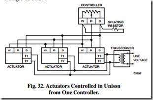
Figure 32 illustrates a circuit for controlling up to six Series 90 actuators in unison from one Series 90 controller. The B to W terminals of the controller are shunted with the appropriate value resistor, depending on the number of actuators in the circuit. This method can control a large bank of dampers requiring more torque than can be provided from a single actuator.
MANUAL MINIMUM POSITIONING OF OUTDOOR AIR DAMPER
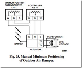
Figure 33 illustrates a circuit for a typical outdoor air damper control system with a manual potentiometer for minimum positioning. Adjusting the potentiometer so that the wiper is at W shorts the potentiometer coil out of the circuit and the outdoor air damper actuator operates normally. The damper closes completely if commanded by the controller. Moving the potentiometer wiper toward B increases the resistance between B on the controller and W on the actuator to limit the travel of the actuator toward closed. The damper remains at the set minimum position even though the controller is trying to close it completely.
A 135-ohm manual potentiometer provides up to a 50 percent minimum-position opening, and a 270-ohm manual potentiometer provides up to a 100 percent minimum-position opening.
STEP CONTROLLER
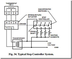
A step controller consists of a series of switches operated sequentially by cams on a crankshaft. Figure 34 illustrates a Series 90 step controller used to stage electric heating elements or compressors. The step controller crankshaft is positioned by a Series 90 actuator through an interconnecting linkage.
When heat is called for at the thermostat, the actuator turns the electric heat elements on in sequence. When less heat is required, the electric heat elements turn off in reverse sequence. If power is interrupted, a spring return in the actuator cycles the step controller to the no-heat position. As power resumes, the loads recycle in sequence to the level called for by the thermostat. The recycle feature assures that the starting loads will not overload the power line.
In some Series 90 step controllers, the recycle feature is accomplished with a relay rather than a spring-return actuator. On resumption of power, after an interruption, the relay deenergizes the loads, drives the controller to the no-heat position, and then permits the step controller to recycle to the position called for by the thermostat.
Step controllers can also be actuated by Series 60 floating controllers.
