MOTOR CONTROL CIRCUITS
APPLICATION
Motor control circuits are used to:
1. Start and stop motors.
2. Provide electric overload and low-voltage protection.
3. Provide interlocks for human safety, equipment protection, and integration with the temperature control system.
EQUIPMENT
STARTERS
The starter is a motor load switching device having one or more load switching contacts and optional, auxiliary, pilot-duty contacts. All contacts are closed by a solenoid which pulls in an armature. Starters are provided to control high current and/or voltage for single and multiple phase motors from a single, low-current and/or voltage contact or switch.
A starter also contains thermal overloads in series with the load contacts. In the event of prolonged excess current draw through any of the load contacts, the overload contact opens, deenergizing the solenoid and stopping the motor. After the overload has cooled and/or the problem has been corrected, the overload reset button can restart the motor.
Starters can also contain a transformer to provide reduced voltage to power the starter control circuit. In addition, they can contain a manual hand-off-auto switch, a push-button start/stop switch, and auxiliary switching contacts.
CONTACTORS AND RELAYS
Relays are load switching devices similar to starters but without thermal overloads. Contactors are heavy-duty relays. These devices switch electric heaters or other equipment that have independent safety and overload protection.
OPERATION
Three basic types of motor control circuits are discussed in the following. This topic is only intended to illustrate general principles. There are many variations for each of these of circuits.
MOMENTARY START-STOP CIRCUIT
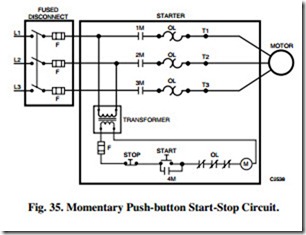
Figure 35 illustrates a momentary push-button start-stop circuit. Both the START and the STOP buttons are spring loaded and return to the positions shown after pressing momentarily. Pressing the START button completes a circuit energizing starter
solenoid M. Contacts 1M through 3M start the motor and contact 4M forms a holding circuit across the START button allowing it to be released. Pressing the STOP button opens the holding circuit, drops out the starter coil M, and stops the motor.
For digital control N.C. and N.O. momentarily actuated relay contacts under computer control are added to the start and stop contacts circuit. The N.C. contact is in series with the stop contact and the N.O. contact is in parallel with the start contact.
An overload in any of the motor coils causes the associated overloads OL to heat up and open the OL contacts, opening the holding circuit, and stopping the motor. Overloads are thermal heaters which allow brief periods of significant overload but their response is too slow to protect the electrical system from a short circuit. The circuit shown includes a separate manually operated, fused (F), line disconnect, for short circuit protection.
HAND-OFF-AUTO START-STOP CIRCUIT
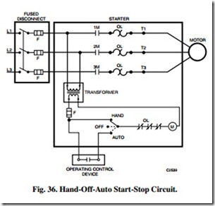
The starter switch in Figure 36 has three positions: HAND, OFF, and AUTO. The HAND position energizes starter solenoid M and starts the motor. The OFF position deenergizes starter solenoid M and stops the motor. The AUTO position allows the motor to be turned on or off as called for by an operating control device (interlock) such as a thermostat, pressure controller, or relay contact. This is the preferred starter circuit when the motor load is under automatic control.
MOMENTARY FAST-SLOW-OFF START-STOP CIRCUIT
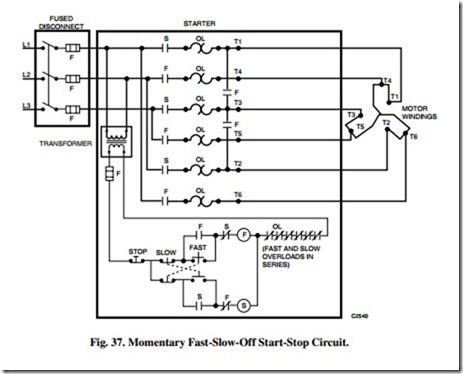
Figure 37 illustrates a momentary, two-speed, start-stop circuit with separate windings for fast and slow motor speeds. Pressing the FAST button closes a circuit energizing starter solenoid F for the fast windings. Pressing the SLOW button closes a circuit energizing starter solenoid S for the slow windings. The holding circuits and the push-button contacts are mechanically interlocked to prevent energizing both sets of windings at the same time. Pressing the STOP button opens both holding circuits and stops the motor.
Where a mechanical interlock does not exist between the holding circuits and push-button contacts, the fast speed start circuit must be opened before energizing the slow speed circuit because of the N.C. slow auxiliary contact wired in series with the fast speed solenoid. A similar situation exists when changing from slow to fast.
CONTROL COMBINATIONS
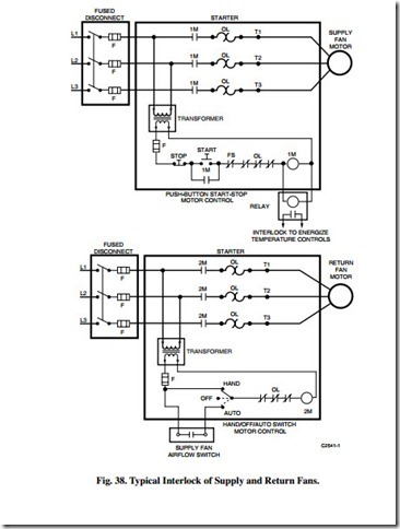
There are many different control combinations for motor control circuits. Figure 38 illustrates a return fan interlocked with the supply fan. In this circuit, the supply fan starts when the START button is pressed energizing starter solenoid 1M.
The return fan will not start until supply airflow is proven. A relay can be added to interlock to the temperature control system. An auxiliary contact on the supply fan starter, when available, can be used for this same function.


